annamal
- 393
- 33
- Homework Statement
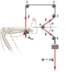
- A leg is suspended in a traction system, as shown below. (a) Which pulley in the figure is used to calculate the force exerted on the foot? (b) What is the tension in the rope? Here T is the tension, wleg is the weight of the leg, and w is the weight of the load that provides the tension
- Relevant Equations
- b) T = m*g. Why?
A leg is suspended in a traction system, as shown in the attached image. (a) Which pulley in the figure is used to calculate the force exerted on the foot? (b) What is the tension in the rope? Here T is the tension, wleg is the weight of the leg, and w is the weight of the load that provides the tension
b) I am not sure why T = m*g. Why wouldn't w = T*sin(theta) --> T = w/sin(theta)?
b) I am not sure why T = m*g. Why wouldn't w = T*sin(theta) --> T = w/sin(theta)?