NotFivehead
- 3
- 0
- Homework Statement
- Measurement technology problems
- Relevant Equations
- There is no single solution because there are multiple problems
1) Describe the Wheatstone bridge circuit and its condition for balance
2) What is shown in the figure? Explain its operating principle. Derive the relationship between the mechanical and electrical parameters.
(Strain gauge belongs to task 2)
3) We are measuring three-phase power using the Aron connection (2-wattmeter method). The power meter specifications are: I(n) = 3 A, U(n) = 300 V, cosφ(n) = 1, scale range = 150°, α₁ = 60°, α₂ = 72°, p(0) = 0,2.
a) What is the application condition for this connection method?
b) What is the active power consumption of the load?
c) What are the reactive and apparent power consumptions of the load?
4) We are measuring resistance using the V-A method. The voltmeter's measurement range is 50 V, and the ammeter's is 1,5 A. The measured voltage is 24 V, and the measured current is 0,8 A. The voltmeter's internal resistance is characterized by 2000 Ω/V, and the ammeter's internal resistance is 0,5 Ω. Both instruments have an accuracy class of 0,5.
a) Determine the measured value of the resistance!
b) Specify the circuit configuration that results in smaller systematic measurement error! Justify your choice! What causes this error?
5) We are measuring a DC voltage of U(measured) = 3 V using the following instruments:
- Deprez voltmeter, accuracy class h(accuracy class) = 0.5, measurement range U(measurement range) = 10 V
- Electrodynamic voltmeter, accuracy class h(accuracy class) = 1.5, measurement range U(measurement range) = 5 V
- 3½-digit digital voltmeter, error ±(0.2% FS + 2D), measurement range U(measurement range) = 20 V
Which instrument allows the most accurate measurement? Justify your choice with calculations!
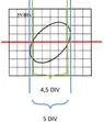
6) The following waveform was observed on the oscilloscope screen:
a) What quantities can be measured based on the displayed waveform?
b) What is the phase difference between the two compared sinusoidal voltages?
(The picture with oscilloscope, belongs to task 6)
2) What is shown in the figure? Explain its operating principle. Derive the relationship between the mechanical and electrical parameters.
(Strain gauge belongs to task 2)
3) We are measuring three-phase power using the Aron connection (2-wattmeter method). The power meter specifications are: I(n) = 3 A, U(n) = 300 V, cosφ(n) = 1, scale range = 150°, α₁ = 60°, α₂ = 72°, p(0) = 0,2.
a) What is the application condition for this connection method?
b) What is the active power consumption of the load?
c) What are the reactive and apparent power consumptions of the load?
4) We are measuring resistance using the V-A method. The voltmeter's measurement range is 50 V, and the ammeter's is 1,5 A. The measured voltage is 24 V, and the measured current is 0,8 A. The voltmeter's internal resistance is characterized by 2000 Ω/V, and the ammeter's internal resistance is 0,5 Ω. Both instruments have an accuracy class of 0,5.
a) Determine the measured value of the resistance!
b) Specify the circuit configuration that results in smaller systematic measurement error! Justify your choice! What causes this error?
5) We are measuring a DC voltage of U(measured) = 3 V using the following instruments:
- Deprez voltmeter, accuracy class h(accuracy class) = 0.5, measurement range U(measurement range) = 10 V
- Electrodynamic voltmeter, accuracy class h(accuracy class) = 1.5, measurement range U(measurement range) = 5 V
- 3½-digit digital voltmeter, error ±(0.2% FS + 2D), measurement range U(measurement range) = 20 V
Which instrument allows the most accurate measurement? Justify your choice with calculations!
6) The following waveform was observed on the oscilloscope screen:
a) What quantities can be measured based on the displayed waveform?
b) What is the phase difference between the two compared sinusoidal voltages?
(The picture with oscilloscope, belongs to task 6)
Attachments

Last edited: