Discussion Overview
The discussion revolves around the discrepancy in rotational speed measurements between a tachometer and an oscilloscope, specifically addressing why the oscilloscope appears to double the rotational speed indicated by the tachometer. The conversation includes technical explanations, hypotheses about the measurement setup, and potential corrections to the measurement process.
Discussion Character
- Technical explanation, Debate/contested, Experimental/applied
Main Points Raised
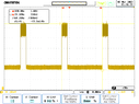
- One participant questions why the oscilloscope shows a rotational speed that is double that of the tachometer, providing specific measurements from both devices.
- Another participant requests details about the experimental setup, including the type of tachometer and motor used, suggesting that the tachometer might be locking to a harmonic of the rotation.
- It is noted that the hall-effect sensor may be sensing only one polarity of the magnet, which could affect the readings.
- One participant asserts that the discrepancy arises because the sensor outputs two pulses for every rotation, implying a need to adjust the oscilloscope's gain to match the tachometer's reading.
- A later reply challenges the assumption that the two pulses per rotation are equally spaced and suggests measuring the period of the signal to determine frequency accurately.
Areas of Agreement / Disagreement
Participants express differing views on the cause of the measurement discrepancy and the appropriate adjustments to the oscilloscope settings. There is no consensus on the exact nature of the problem or the solution.
Contextual Notes
Participants have not provided a complete description of the experimental setup, and there are unresolved questions regarding the specific characteristics of the tachometer and motor being used. The discussion includes assumptions about the behavior of the hall-effect sensor and the nature of the output signal.