Need an electromagnet to play Chess

  • Thread starter Thread starter queenidog
  • Start date Start date
  • Tags Tags
    Electromagnet
AI Thread Summary
The discussion centers on creating a "Phantom" chess game using an electromagnet to move pieces, with players having different polarity magnets. The creator has calibrated their setup but struggles with the electromagnet's strength, finding commercial options inadequate compared to an old solenoid. They plan to build a custom coil using AWG#38 wire but are confused by calculations suggesting low magnetic field strength. Suggestions include using pulsed operation to increase the electromagnet's effectiveness and considering a hybrid approach with permanent magnets. The complexity of the chess game's mechanics, including differentiating player colors and handling special moves, adds to the project's challenges.
queenidog
Messages
18
Reaction score
5
I'm making a "Phantom" chess game where corexy mechanism holding an electromagnet pulls the pieces around. White and Black players have different polarity magnets, N and S and my electromagnet uses H-bridge to change it's polarity. Also using PWM from an Arduino Mega to control it.

EVERYTHING is ready and calibrated except I don't have a good electromagnet. I tried the commercial "button" type with "pulls" of 25kg, but these do not work. What is CLOSE to working is an old solenoid taking 1/4 the current and providing 3x the magnetism. Measured with my Gauss meter the commercial types are ~500 Gs at 1.5 A/12V, whereas my solenoid is 1500 Gs at 250mA/12V. All the details of my construction, including a side view showing the sandwich of aluminum plate, Hall sensor PCB board, acrylic cover, and player on very top is here on my website: https://www.raiderracing.com/Engineering/PhantomChess.html (Go to Fourth Build, as that is where I'm at). There is no facility here to upload a photo of the "sandwich" but you can see at the link.

The current EM (solenoid) can pull the players around through the 2mm aluminum plate, but when I add the PCB with Hall sensors on it, and a 2mm piece of acrylic, the pieces don't move. The magnets in the players are 8x3mm (not sure what grade, but they are neodymium) and have a metal surround on the base to prevent flux leaking out the sides to other players.

The extra thickness of the acrylic top cover and the sensor board is about 6mm (to92 sensors are bumpy, contributing to distance). Reading on opposite side of aluminum plate is 350 Gauss. (a 2 mm acrylic sheet is about 250 Gauss), so I've got little to work with and need more Gas...Gauss.

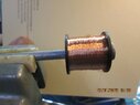
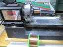
I want to make my own coil with bobbin app 30mmH x 30 mmD using AWG#38 wire with a max current of 130 mA. I can make the bobbin with my 3D printer and will use a plunger from one of my many surplus solenoids for central core. Using a few different on-line calculators I come up with numbers I don't agree with. E.g. 3000 turns of this wire only gives me a field strength of 163 Gauss (16366 uT). Way, way too low. I have 5300 feet (2409M) of #38 wire with a resistance of 2.4 ohms/m according to manufacturer.

So...any idea where I'm going wrong here? Any ideas on how to make this electromagnet? Where do I go from here, other than making the coil and seeing how it works?
 
Last edited by a moderator:
Engineering news on Phys.org
To solve your problem, I can suggest the following. In addition to the online calculator, it makes sense to find a complete guide to calculating electromagnets. This will allow you not only to enter the initial data and get the result, but also to understand the physics of the process and the design features. From personal experience, I can say that the creation of an electromagnet, as a rule, is always associated with the creation of a prototype, the design of which later has to be slightly modified. Thus, the optimal plan is as follows: 1) perform an accurate calculation of the electromagnet; 2) create a prototype and test it; 3) refine the prototype if necessary.
 
Welcome to PF.

queenidog said:
There is no facility here to upload a photo of the "sandwich"
Yes there is. Just use the "Attach files" link below the Edit window.
 
I don't see the Attach files link. Could it be because this is my first post? (Other forums don't allow posting until some credentials are earned.)
Thanks Ivan. That was a Michael Faraday answer.
 
queenidog said:
White and Black players have different polarity magnets, N and S
How do you handle situations where you have to jump a Knight over other pieces (and there is no clear path to move the Knight around other pieces? Like from the opening position...
 
  • Like
Likes sophiecentaur and Ivan Nikiforov
The chess layout is composed of 40 mm squares, the "men" are 18mm (custom made on 3D printer) so they slide in between other players. The software also allows for "en-passant" and castle-ing. A collaborator in Argentina worked on the software, my weak point, but he is also having issues with electromagnets and is waiting for me to make mine.
 
The strength of an electromagnet is determined by the number of ampere turns: Fm=I*W. If the electromagnet has insufficient force, there are two ways to increase it.: 1) increase the number of turns, with a constant current; 2) increase the current, with a constant number of turns. Both of these options are associated with an increase in the amount of copper and the size of the coil. The complexity of your situation lies in the fact that it is not known what force of attraction in Newtons an electromagnet should have for a given value of magnetic induction in Tl. It seems to me that it will not be possible to solve the problem without a prototype. By the way, it may be easier to make a prototype than to go into endless calculations...
 
Gotcha. That's next on my list. I was hoping to "figure it out" before making a prototype as this Amazon purchase (the wire) was not cheap. I can see this very fine wire breaking halfway through the spin onto a bobbin. Swearing a lot comes next.
 
With a current of 130mA and a number of 3000 turns, the magnetomotive force is 390 ampere turns. It's a small force. I can suggest an option to increase it, without additional costs for a copper wire. The idea is to apply large current pulses. Your electromagnet doesn't work all the time, but only when the pieces move. Therefore, this mode of operation eliminates overheating of the windings and allows large current pulses. Perhaps it makes sense to simply increase the voltage that you apply to the electromagnet, say by 30% or 50%.
 
  • #10
I assume you have a core structure to concentrate your B-field. If not, you probably should. Something like this:
1737583365804.png


I find it kind of hard to believe that you can build your own that performs better than what you can buy. It sounds like a pretty standard application.

If you choose pulsed operation, keep your rms current below the dc current rating. Resistive heating of the magnet wire is the limitation. The aluminum plate may be a problem for operation at high frequency because of induced eddy currents canceling your field.
 
  • #11
Why an electromagnet? Permanent magnets will work and might be easier, you would have to lift them away from the board to disconnect. Or maybe a hybrid approach with an electro magnet plus a permanent magnet?

I did a quick experiment that worked well with some Nd magnets and 3mm Lexan I had lying around; this stuff is cheap. Two magnets worked well, although friction is also an issue, sliding required some force. But a bit of felt or Teflon could help a lot. A magnet and an iron piece also worked in my case. There was some spatial lag, with the pieces stopping before they were in complete alignment. The tangential force is weak compared to the normal force. This will be true for either type.

PXL_20250122_221935021.jpg

PXL_20250122_222306821.jpg
 
  • Like
Likes Ivan Nikiforov
  • #12
I have to differentiate between a white and black player so one has a South magnet, the other a north magnet. Which one gets selected depends on the polarity of the electromagnet: one way it picks up white, the other way black. A permanent magnet which DOES work well is static, unless I put in a servo switcher thingy to get the other pole. I have limited area for the magnet because the entire corexy layout has a particular dimension that allows for 40mm squares - just. If I make the magnet holder larger, it will hit the sides of the layout.
 
  • #13
DaveE said:
I assume you have a core structure to concentrate your B-field. If not, you probably should. Something like this:
View attachment 356226

I find it kind of hard to believe that you can build your own that performs better than what you can buy. It sounds like a pretty standard application.

If you choose pulsed operation, keep your rms current below the dc current rating. Resistive heating of the magnet wire is the limitation. The aluminum plate may be a problem for operation at high frequency because of induced eddy currents canceling your field.
That's the kind I have, 3 of them actually and they all have less magnetism than the small solenoid I had. So what's different? Gotta be the # of turns of wire. The EM shown takes about 1.5 A. Must be low resistance, big wires.
 
  • #14
queenidog said:
I have to differentiate between a white and black player
Why? Your computer knows what they are and where they are. First you'll have to go to the right place and then you can grab whatever is there, right? Sorry, I'm not understanding this part.
 
  • #15
I can do that (concentrate the field). I do that with the players now. I will be using PWM in a sort of pulsed mode since the magnet only has to work when it is moving a player around.
 
  • #16
DaveE said:
Why? Your computer knows what they are and where they are. First you'll have to go to the right place and then you can grab whatever is there, right? Sorry, I'm not understanding this part.
That's what I thought at first, basically an array that gets updated on every move, but the Micromax code, written by others differentiates the two and so this differentiation must be maintained for the "supervisory code", the one that actually moves the players. The system uses a standard Chess algorithm and I'm using modified code by others as well.
 
  • #17
queenidog said:
That's what I thought at first, basically an array that gets updated on every move, but the Micromax code, written by others differentiates the two and so this differentiation must be maintained for the "supervisory code", the one that actually moves the players. The system uses a standard Chess algorithm and I'm using modified code by others as well.
Hum... OK. Complex historical systems are a PITA to work with. That's why we have the recurrent laryngeal nerve in giraffes and people still writing COBOL code.

But they still have to go to the right place first, grab something, and move it to the correct place. Why not just "rectify" the command polarity and just grab the piece. How is "move the white piece at A4 to A5" different from "move the piece at A4 to A5"? Do the chess pieces have to have different polarity magnets (or any magnet, for that matter)? Do you make the chess set?

Just as an aside, since there are a lot of chess pieces and only one "grabber" mechanism. It would be cheapest to just put iron in the pieces and spend more for a good "grabber" magnet, I think, maybe.
 
  • #18
It has to do with more complex chess moves like en passant, castleing and getting a Queen (by pawn reaching the other side). Remember too that if a black eats a white player, that position is now black, not white. Check out my webpage. I refer to the original Instructable which me and my collaborators in Argentina and Malaysia have modified intensely. The original used reed switches, we use Hall effect switches and because a South pole creates a different current than a North pole, we can tell what color player is on a square. It's actually simpler than calculating a 64 object array every move. https://www.raiderracing.com/Engineering/PhantomChess.html
 
  • Skeptical
Likes DaveE and hutchphd
  • #19
DaveE said:
Hum... OK. Complex historical systems are a PITA to work with. That's why we have the recurrent laryngeal nerve in giraffes and people still writing COBOL code.

But they still have to go to the right place first, grab something, and move it to the correct place. Why not just "rectify" the command polarity and just grab the piece. How is "move the white piece at A4 to A5" different from "move the piece at A4 to A5"? Do the chess pieces have to have different polarity magnets (or any magnet, for that matter)? Do you make the chess set?

Just as an aside, since there are a lot of chess pieces and only one "grabber" mechanism. It would be cheapest to just put iron in the pieces and spend more for a good "grabber" magnet, I think, maybe.
I have a Scara arm that I will teach to play chess (using Swordfish engine) after I get my Phantom chess working.
 
  • #20
DaveE said:
Why not just "rectify" the command polarity and just grab the piece.
Because then the electromagnet would have to be twice as strong; this way the attractive force is the sum of the two fields (at least up to the point that one of the fields is not strong enough to cancel the other one).

@queenidog, is it practical to replace one, or both, of the stiff sheets with a thinner sheet? For instance a thin sheet of Glass/Epoxy printed-circuit board material is available in 0.3mm or less thickness. As the field strength decreases as the square of distance, this may be all that is needed.

https://www.bestpcbs.com/products/extra-thin-pcb.htm
(found with:http://www.google.com/search?hl=en&q=thin+pcb)

Also, for winding the solenoid, make sure the magnetic circuit is thick enough so it is not magnetically saturated; this is dependent on field strength, magnetic properties of the material, and its cross-section.

Sounds like an interesting project!

Cheers,
Tom

p.s. Please keep us updated on the project, we like to learn too!
 
  • #21
Tom.G said:
Because then the electromagnet would have to be twice as strong
Of course, If the magnet is backwards. That's why I asked about building your own chess set.
 
  • #22
Tom.G said:
Because then the electromagnet would have to be twice as strong; this way the attractive force is the sum of the two fields (at least up to the point that one of the fields is not strong enough to cancel the other one).

@queenidog, is it practical to replace one, or both, of the stiff sheets with a thinner sheet? For instance a thin sheet of Glass/Epoxy printed-circuit board material is available in 0.3mm or less thickness. As the field strength decreases as the square of distance, this may be all that is needed.

https://www.bestpcbs.com/products/extra-thin-pcb.htm
(found with:http://www.google.com/search?hl=en&q=thin+pcb)

Also, for winding the solenoid, make sure the magnetic circuit is thick enough so it is not magnetically saturated; this is dependent on field strength, magnetic properties of the material, and its cross-section.

Sounds like an interesting project!

Cheers,
Tom

p.s. Please keep us updated on the project, we like to learn too!
Because the layout is so large (because of the corexy mechanism), 2-3 mm acrylic plastic sags in the middle. I bought some 6mm plastic, doesn't sag but doesn't work. WAY too thick. So I went with aluminum sheet since it is paramagnetic and won't hold magnetism. Of all the products I tested, the aluminum was the BEST and it is stiff as hell. I had hoped to use acrylic to show all the mechanism below, but as mentioned, not practical. Glass was a possibility and so was a 2 part cover, thick on the outside with a center piece that is thin with the chess board laid out on top of it. My sensor board is 0.6mm thick, very floppy. I ordered it this way JUST for this project. PCBs are standard 1.6mm thick.

What do you mean when you say, "make sure the magnetic circuit is thick enough"?
 
  • #23
UPDATE Jan23
I made a coil with #38 wire, spun on a bobbin I made on 3D printer, of size that would fit in my Chess game. I calculated 21,200 turns (I used a slow turning lathe to load the bobbin), measured 1600 ohms, which worked out to 666 meters of wire. I did not wind wire on metal core (I tried but failed because lathe chuck wouldn't grab the bobbin), using only the plastic open air core. Measured Gauss at 271 @24 volts. current was only 8 mA. Here's the thing: more current or more turns gives more field strength but more turns results in more resistance so less current can be used. I can increase voltage but there is a limit. To obtain the max current of 130mA in a 1600 coil would require a power supply of 208 volts. So I could get larger wire, #34 perhaps. It has less resistance but is thicker so I'll have fewer turns! I'm also going to wind more #38 onto a metal rod instead of having a rod in a plastic sleeve as I did. Left photo is my coil on a rod, under test.
 

Attachments

  • IMG_1552.JPG
    IMG_1552.JPG
    38.1 KB · Views: 30
  • IMG_7072.JPG
    IMG_7072.JPG
    79.1 KB · Views: 40
  • Like
Likes Ivan Nikiforov
  • #24
queenidog said:
What do you mean when you say, "make sure the magnetic circuit is thick enough"?
I was thinking that the electromagnet frame would be ferromagnetic material (Iron maybe) in the shape of a cup with a center post. The center post would be the core of the electromagnet and the cup part would concentrate the field at the Chess board.

You don't want the ferromagnetic material to get magnetically saturated in use, you lose field strength at the working end that way - and the field of a stronger/bigger solenoid does not help because the field can not get to where it's needed.

So calculate/measure the field strength of the solenoid and choose the frame material and size to get all that flux to the work area.

Cheers,
Tom
 
  • #25
queenidog said:
UPDATE Jan23
I made a coil with #38 wire, spun on a bobbin I made on 3D printer, of size that would fit in my Chess game. I calculated 21,200 turns (I used a slow turning lathe to load the bobbin), measured 1600 ohms, which worked out to 666 meters of wire. I did not wind wire on metal core (I tried but failed because lathe chuck wouldn't grab the bobbin), using only the plastic open air core. Measured Gauss at 271 @24 volts. current was only 8 mA. Here's the thing: more current or more turns gives more field strength but more turns results in more resistance so less current can be used. I can increase voltage but there is a limit. To obtain the max current of 130mA in a 1600 coil would require a power supply of 208 volts. So I could get larger wire, #34 perhaps. It has less resistance but is thicker so I'll have fewer turns! I'm also going to wind more #38 onto a metal rod instead of having a rod in a plastic sleeve as I did. Left photo is my coil on a rod, under test.
With a number of turns of 21200 and a current of 0.008 A, the magnetomotive force is 170 ampere turns. The magnetic induction generated by this force depends on the core material and the average length of the magnetic line. A magnetic line is a line along which a magnetic field closes. If you insert a long core into the coil as shown in the photo, the length of the magnetic line is very long, so the magnetic induction is weak. I suggest you cut off the rod according to the height of the coil, that is, make sure that the core is inside the coil and does not protrude beyond its limits. You can increase the magnetic induction in the following way. You can apply the winding in two layers. That is, the first winding of 10600 turns will give a current of 0.016 A, the second winding of 10600 turns will give a current of 0.016 A. These windings are connected in parallel. You will get the same number of turns, but the current will be 0.032 A, that is, 4 times more. In the future, you can recalculate these two windings by one winding of a wire with a larger cross-section. This is the second option. First, I would suggest that you make a proper low carbon steel core and check the result.
 
  • #26
If your electromagnet is too strong during the test, you can reduce the number of turns, and the current can be limited, for example, by using a resistor connected in series or using a transistor.
 
  • #27
Ivan Nikiforov said:
With a number of turns of 21200 and a current of 0.008 A, the magnetomotive force is 170 ampere turns. The magnetic induction generated by this force depends on the core material and the average length of the magnetic line. A magnetic line is a line along which a magnetic field closes. If you insert a long core into the coil as shown in the photo, the length of the magnetic line is very long, so the magnetic induction is weak. I suggest you cut off the rod according to the height of the coil, that is, make sure that the core is inside the coil and does not protrude beyond its limits. You can increase the magnetic induction in the following way. You can apply the winding in two layers. That is, the first winding of 10600 turns will give a current of 0.016 A, the second winding of 10600 turns will give a current of 0.016 A. These windings are connected in parallel. You will get the same number of turns, but the current will be 0.032 A, that is, 4 times more. In the future, you can recalculate these two windings by one winding of a wire with a larger cross-section. This is the second option. First, I would suggest that you make a proper low carbon steel core and check the result.
Wow! Good advice. Actually the nail in the photo was only used to hold the coil up and it was my intention to replace it with a piece that fit the dimensions of the bobbin. Today I'm winding another coil directly onto the metal rod. Good idea about the parallel coils. I will try that too. I assume the coils would be applied in the same direction?
 
  • #28
Tom.G said:
I was thinking that the electromagnet frame would be ferromagnetic material (Iron maybe) in the shape of a cup with a center post. The center post would be the core of the electromagnet and the cup part would concentrate the field at the Chess board.

You don't want the ferromagnetic material to get magnetically saturated in use, you lose field strength at the working end that way - and the field of a stronger/bigger solenoid does not help because the field can not get to where it's needed.

So calculate/measure the field strength of the solenoid and choose the frame material and size to get all that flux to the work area.

Cheers,
Tom
Thanks for good advice. I had not thought about a metal frame, actually but in looking at other EMs and even solenoids, most of them have metal frames. I can do that. Another experiment!
 
  • #29
berkeman said:
How do you handle situations where you have to jump a Knight over other pieces (and there is no clear path to move the Knight around other pieces? Like from the opening position...
We're still waiting for an answer about knight moves. If the knight can't jump when necessary, other pieces may need to shuffle out of the way. Your software wizard may need to sort that out for you. :wink:
 
  • #30
sophiecentaur said:
We're still waiting for an answer about knight moves
No, he answered it in the next reply below my comment. The pieces are slim enough that they can be slid between the other pieces, so the Knight does not need to do any jumping over other pieces.
 
  • #31
queenidog said:
I assume the coils would be applied in the same direction?
Yes, you're right, the wire is wound in one direction.
 
  • #32
sophiecentaur said:
We're still waiting for an answer about knight moves. If the knight can't jump when necessary, other pieces may need to shuffle out of the way. Your software wizard may need to sort that out for you. :wink:
Well I did answer this question before (maybe it was on the Enginerring forum) but here it is: The chess squares are 40mm across, the players (all custom made by me on a 3D printer) have bases 18mm across so they are 11 mm away from an edge. 2x11= 22 mm, 4mm extra to move the player between the others. The originator posted a video of this action, which is what got me so involved in the first place! Go here:

 
  • Like
Likes Ivan Nikiforov and sophiecentaur
  • #33
I have failed. I made another coil, with two layers and a metal core Not being able to determine how much was in each, I just winged it and wound what I thought was the same amount each time. NOT! Coil1 was 358 ohms and coil2 was 1180 ohms, or 149m and 492 m respectively. Total for the two coils in parallel @12V was 362 Gs, @ 24V it was 749Gs. This still pales in comparison to the solenoid (shown in photo on left) which is 1122 Gs @12V, yet is 1/4 the size! If I used a 48 volt supply, yeah that would put my coil higher.
Since I'm nowhere near Edison's 10,000 things that didn't work, I will try again with a different core and try and wind the same amount each time. Since the revs on my lathe are constant, I'll just time everything, say 15 minutes for each coil. I might also use bigger wire, like #36 instead of #38.
If I put a metal can around my coil, like the solenoid, would that help? I'll try that too.
 

Attachments

  • IMG_1560.JPG
    IMG_1560.JPG
    68.6 KB · Views: 31
  • #34
I don't think you've failed. You've almost got the right design. The solenoid on the left has a current of 250mA, and earlier you set the goal to create a solenoid with a current of no more than 130mA. The result you have obtained is very important. Previously, you had 271 Gs, now you have increased this value almost 3 times to 749 Gs. If you made two identical windings, the increase should be 4 times, since the number of turns remained the same 21200, and the current would increase 4 times from 8mA to 32mA. In general, the data obtained needs to be clarified. If the first coil had 1600 ohms, then at 24V the current should have been: 24/1600 = 15mA. The specific resistance of AWG38 is 2.16ohms/m. For 1600ohm, this gives a length of 740m. The following data series is obtained: 1) AWG38 740m 15mA; 2) AWG35 740m 30mA; 3) AWG32 740m 60mA; AWG29 740m 120mA.
 
  • #35
Thanks Ivan for all your help. It's been informative.
HOWEVER, everyone, I'm changing tactics. After achieving 1738 Gs with an EM taken from a relay and modifying the center rod, I find that this is JUST MARGINAL to move the player effectively. So, as Dave E. recommended once (and I was aware of but thought it too difficult...) I'm going the servo/permanent magnet route.
With a 180 degree servo I can switch in a north magnet or a south magnet. Easy peazy really, as long as I can get the servo in the spot made for the EM, and also that the flipping doesn't catch an edge when the magnet is 5 or 10 degrees from it's destination. The magnets have to come to the same position so that the coding doesn't become horrendous to compensate for two magnets that do not align.

FYI, compare the 1738 Gs EM with these numbers, for various permanent magnets I have: 13x6 mm: 4124, 16x3: 2979, 16x5 (magnets for cabinet doors): 3900, and 10x3: 2380. I tested the latter with my test "sandwich" consisting of 2mm Aluminum, 2.5mm sensor board, and 3 mm acrylic sheet with player on top. works like a CHARM! I chose the smallest magnets for less mass, thus smaller servo, fewer problems swinging up into place. I'll post a photo when I get it working.
 
  • Like
Likes Ivan Nikiforov
  • #36
queenidog said:
I'm going the servo/permanent magnet route.
With a 180 degree servo I can switch in a north magnet or a south magnet. Easy peazy really
One thing to keep in mind is that the permanent magnets may become a bit demagnetized over time due to the physical movement in and out of other static magnetic fields. I'm not sure how to quantify it, but I think as long as your magnets are ~50% more powerful than they need to be, that the gradual demagnetization over time should not affect the operation of your board mechanism.

https://www.duramag.com/techtalk/magnet-design/causes-demagnetization-permanent-magnets/
 
  • Like
Likes Ivan Nikiforov
  • #37
Wow! I didn't know that. thanks for the info. I have a bunch of the magnets I plan to use though, so they are easily replaceable. I have a Gauss meter to test them
 
  • #38
queenidog said:
If I put a metal can around my coil, like the solenoid, would that help? I'll try that too.
It will concentrate the magnetic fields. In your design the opposite pole of the magnetic field is all the way on the other end of the coil. If you put it in a ferromagnetic cup then the opposite poles will be right next to each other. You will probably want to put the chess piece magnets in a cup with the same diameter as the one over the coil to further improve the attraction.

BoB
 
Back
Top