Discussion Overview
The discussion revolves around understanding a method used by a professor to analyze op-amp circuits, specifically relating to the application of Thevenin's theorem and nodal analysis. Participants are seeking clarification on the logic behind the professor's approach and how it leads to a specific voltage calculation.
Discussion Character
- Exploratory
- Technical explanation
- Homework-related
Main Points Raised
- Some participants express confusion over the professor's method, noting that they can arrive at the same answer using nodal analysis but find the professor's approach more elegant.
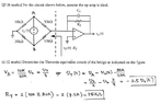
- One participant describes the Thevenin equivalent circuit, outlining the components involved, including the voltage generator and the resistor, and how they relate to output voltage and current.
- Another participant attempts to follow the professor's logic regarding the voltage at node $V_A$, questioning how the relationship $V_A=\frac{10}{40}V_s=\frac{V_s}{4}$ is derived.
- A participant suggests that if the output node is open, the current through the resistors must be the same, leading to a conclusion about the voltage relationship between the resistors.
Areas of Agreement / Disagreement
Participants generally express confusion and seek clarification on the professor's method, indicating that multiple interpretations or understandings exist regarding the analysis of the circuit. No consensus is reached on the explanation of the professor's approach.
Contextual Notes
Participants reference specific calculations and relationships between voltages and currents in the circuit, but the discussion does not resolve the underlying assumptions or steps in the analysis.