[] Output current of transistor

Join the discussion
Registration is free. Ask a follow-up in this thread, or start your own.
11 replies · 2K views
cuongbui1702
Messages
31
Reaction score
0
Warning: Homework template must be used for all homework questions
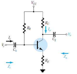
My teacher gave me this picture below. My question is why Io go through Rc but does not go through C2
Mtb5V_zpskj3obfmb.png
 
Physics news on Phys.org
gneill said:
Presumably C2 is open circuited in this case (no connection at Vo).
But why Ii is not equal 0 because of C1
 
cuongbui1702 said:
But why Ii is not equal 0 because of C1
##I_i## would be assumed to be some injected input current.

I realize that it may seem to present contradictory notions, but this is a just a convention that's often used to set up the scenario for analysis of a circuit: Some signal is assumed to be present at the input and the output is unloaded.
 
  • Like
Likes   Reactions: cuongbui1702
cuongbui1702 said:
My teacher gave me this picture below. My question is why Io go through Rc but does not go through C2
You could say Rc represents the load. The capacitor provides a handy point where you can imagine monitoring the output voltage.

When you connect a resistive load between the capacitor and ground, this can be accounted for by just reducing Rc in your AC voltage-gain analysis.
 
do not forgot that with capacitors i=(1/C)Cdv/dt. so you could say say that there will be a Ii when Vi changes.

io does not go through the capacitor because it is an open circuit on the other side, so the current has nowhere to flow.

This is not important for you solving the problem but it might help prospective. the purpose of circuits like this are to amplify an AC signal. The C1 is in there to block DC gain from entering the amplifier. Rb, Re and Rc will bias your transistor so it is operating in the correct region. C2 will prevent a DC voltage from leaving the amplifier. Since we are dealing with AC gains, all components will affect the gain. also note that in many cases circuits like this are attached to a high impedance circuit on the output, so it can be modeled as an op circuit.
 
So almost is assuming, and Io = ic( AC of IC, IC is DC current going through RC). That makes me messing up. When I take a Rload, where is Io, does it continue going through Rc?
 
is this for a homework assignment. If it is then the knowledge that current cannot flow through an open current should be enough.

If this isn't for a homework assignment, then when you add a load the current will only flow through the capacitor when the voltage across the cap changes, which will be due to a change in input voltage. The Io signal will have both a DC and AC component to it while the circuit is operating.
 
  • Like
Likes   Reactions: cuongbui1702
Thank for your answers. And one more question, my teacher said me that: when I calculate Zin or Zout, I must have 1 condition such as: Iin =0, or Iout = 0. Why I must have this condition?
 
cuongbui1702 said:
My teacher gave me this picture below. My question is why Io go through Rc but does not go through C2
Mtb5V_zpskj3obfmb.png
This is a dc problem. DC does not go thru a capacitor.
Plus the fact that there is no connection with one of C's terminals so AC current would not go through it either.