Partially closed pump discharge valve question

Join the discussion
Ask a follow-up here, or get your own question answered by working scientists, mathematicians and engineers — people, not an autocomplete.
Real named experts · corrections over time · the nuance an AI answer skips
7 replies · 5K views
help_pls
Messages
9
Reaction score
1
Hi all,

I have a question about the effect of partially closing a pump discharge valve on the system curve, wondering if you guys can help me out.
RyY3oNC.png


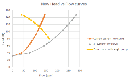
Right now I have the yellow pump curve and the orange 2 inch system curve , producing around 120 gpm against around 110 ft of head. If I expand the piping from 2 inch to 3 inch I end up with the grey system curve. The grey system curve doesn't intersect with the pump curve so this way of operating is not possible in my understanding; However, using the grey system curve, if I partially close the pump discharge valve to artificially increase the head so that the total head becomes 110 ft, would the new operating point be the same as before (120 gpm against 110 ft of head)? Similarly, if I partially close the discharge valve so that the total head becomes say 100 ft, would the operating point be around 130 gpm against 100 ft of head?

Any help is appreciated, thank you guys.
 
Physics news on Phys.org
While the curves don't intersect, that does not indicate that you cannot operate the system with the larger pipe it only indicates that regardless of how much the discharge backpressure head is reduced below 80 ft, the delivery of the pump will not exceed its design maximum of what appears on the chart to be about 160 gpm.
 
anorlunda said:
I think you can answer your own question. Just extend your thinking to the point where the valve is almost closed, then fully closed. What happens to the operating point?
So the system curve will shift left-ward depending on how much you close the valve right?
 
JBA said:
While the curves don't intersect, that does not indicate that you cannot operate the system with the larger pipe it only indicates that regardless of how much the discharge backpressure head is reduced below 80 ft, the delivery of the pump will not exceed its design maximum of what appears on the chart to be about 160 gpm.
Ok, but it far from optimal right, due to poor efficiency, possible dmg to the pump etc., I'd be better off throttling the discharge?
 
If you don't require the maximum delivery rate, throttling is a good idea to get the minimum operating power cost at your desired flow rate.
 
What JBA says is spot on. One thing to consider, bearing in mind that it all is a little theoretical at the finer details. Consider that the total head is a sum of three different figures. The first is the topographical head which is a function of the height of lift you are operating against. This number will not change no matter what size pipe you are using. The second would be the resistance head, this is a function of the piping as an overall system including all bends. It also will be affected by the interior finish of the piping and the size. The last would be the induced head which is the back pressure that is created by the valve used as an adjustable orifice.
The larger pipe with the longer radius bends will in general be easier to move fluids. One could use the valve to adjust the head pressure and create the most efficient flow for your application.
 
help_pls said:
The grey system curve doesn't intersect with the pump curve so this way of operating is not possible in my understanding;
No, the pump curve goes all the way down to zero head on one end and zero flow on the other. What you appear to have there is actual test data - usually manufacturers will extrapolate the rest of the curve, but they didn't here.

Caveat; you would need to make sure your motor is big enough to handle that operating point.