PLL - How to find all the gains of a PI corrector and fix Ki ? MATLAB

AI Thread Summary
The discussion focuses on adjusting the gains Kp and Ki in a second-order Phase-Locked Loop (PLL) implemented in MATLAB. The user seeks a formula to ensure these gains adapt correctly to changes in bit rate and sampling frequency while maintaining desired damping characteristics. A key point raised is the importance of incorporating the zero-order hold (ZOH) effect when sampling, which impacts the integral and derivative gain terms. The user has attempted to modify the gain calculations but is struggling to achieve the expected performance across different configurations. The conversation highlights the need for a deeper understanding of digital control principles related to PLL design.
Wrlccywrlfh
Messages
2
Reaction score
2
Homework Statement
Find the relationship that gives Ki as a function of all the parameters to obtain the correct impulse response
at a phase step regardless of the rate and the number of samples per symbol
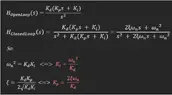
Relevant Equations
H(s) = (Kd(Kp*s + Ki)) / (s^2 + Kd(Kp*s + Ki))
Kp = 2*Xi*wn / K
Ki = (wn)^2 / K
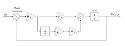
Hello everyone, it's not really for my homework (because I'm not at school anymore) but I'm new and I don't know how to start a new forum. I've never done automatic before and I need help.

I have a 2nd ordre PLL on MATLAB, with an NCO and a PI corrector; the PLL works via the Mid/End algorithm (that's part is ok). I need to find the link between the theoretical formulas and their values in the code to find the value of the gain Ki, and possibly that of Kp if it's not correct. Unfortunately, I can't find the formulas so that my gains are always adapted when I change the rate or the number of samples per symbol, while I'm sure that it exists. Xi and wn are fixed. I thing the problem is K (Kd * Knco), which must not be correct, but I know that sum(g) is.

Here's the code :
Matlab:
% Modulation
rng(0);

rate = 1e6;
fe = 80e6;
N_SR = fe / rate;
nb_bits = 1000;
Tb = 1/rate;
Ts = 1/fe;

% =========== No need help part ===========
bitstream = 2 * randi([0 1], 1, nb_bits) - 1;
nrz = kron(bitstream, ones(1, N_SR));
h = 0.7; L = 1; v = 0:(L*N_SR - 1);
g = (1 / (2 * L * N_SR)) * (1 - cos(2 * pi * v / (L * N_SR)));
s_filtered = conv(nrz, g);
phi = 2 * pi * h * cumsum(s_filtered) / N_SR;
S_ideal = exp(1i * phi);
phi_ideal = unwrap(angle(S_ideal));
S = exp(1i * phi_ideal);

% Phase offset
phi_offset = pi;
S = S * exp(1i * phi_offset);

% Demodulation
fc = 1e6;
omegac = fc / (fe/2);
order = 90;
f_reject = 1.2e6 / (fe/2);
f = [0 omegac f_reject 1];
a = [1 1 0 0];
w = [1 100];
b = firpm(order, f, a, w);
S_real_filtered = filter(b, 1, real(S));
S_imag_filtered = filter(b, 1, imag(S));
S_filtered = S_real_filtered + 1i * S_imag_filtered;
phi_rec = unwrap(atan2(imag(S_filtered), real(S_filtered)));
freq_inst = diff(phi_rec);
freq_inst(end+1) = freq_inst(end);
freq_inst = freq_inst / (h*pi);
% Filter (LP)
filtre_PB = fir1(10, 0.1);
freq_filtered = conv(freq_inst, filtre_PB, 'same');


% ============= Need help part =============

Xi = sqrt(2)/2;     % Fixed
wn = rate*1e-3;  % Fixed
Kd = sum(g);
K0 = Ts/Kd;          % Not used
Knco = Kd/K0;     % Not used

Kp = (2*Xi*wn) / (Kd);
Ki = (wn)^2 / (Kd*fe);

incr0 = 1/(N_SR);
incr = incr0; % Initial release of the VCO

alpha = 0;    % alpha to detect when there is a new symbol
Aq_mid = 0;
Aq_end = 0;
alpha_prec = 0;
top_symb = 0;
S_end = 0;
S_mid = 0;
S_end_prec = 0;
S_mid_prec = 0;
k = 1;
err_ph = 0;
sum_err_ph = 0;
err_phi_rad = 0;
incr_hist = 0;
nco_sync = zeros(1, length(phi_rec)-1);
bitsync = zeros(1, length(phi_rec)-1);
decalage = zeros(1, length(phi_rec)-1);

for n = 1:length(phi_rec)-1
   alpha = alpha + incr;
   top_symb = 0;

   % Update Mid/End
   if alpha >= 0.5 && alpha_prec <0.5
      S_mid_prec = S_mid;
      S_mid = Aq_mid;
      Aq_mid = s_filtered(n);
   else
      Aq_mid = Aq_mid + s_filtered(n);
   end

   if alpha >= 1.0
      alpha = mod(alpha,1.0);
      S_end_prec = S_end;
      S_end = Aq_end;
      Aq_end = s_filtered(n);
      top_symb = 1;
      k = k+1;
   else
      Aq_end = Aq_end + s_filtered(n);
   end

   if top_symb == 1
      nco_sync(n) = 1;
      if (S_end_prec >0 && S_end <=0 )
         err_ph(k) = S_mid/N_SR;
      elseif (S_end_prec <= 0 && S_end > 0 )
         err_ph(k) = -S_mid/N_SR;
      else
         err_ph(k) = err_ph(k-1);
      end
      sum_err_ph = sum_err_ph + err_ph(k);
      incr = incr0 - Kp*err_ph(k) - Ki*sum_err_ph;
   end
   alpha_prec = alpha;
end

% Bode
% Transfer function (open)
p = tf('s');
G = tf([Kd*Kp Kd*Ki], [1 Kd*Kp Kd*Ki]);

figure;
subplot(2,1,1);
bode(G, {0, 1e7}); % Plage de fréquences de 1 kHz à 10 MHz
title('Bode diagram - open loop');
grid on;
subplot(2,1,2);
bode(H, {0, 1e7});
title('Bode diagram - closed loop');
grid on;

% Error phase plot
figure;
plot((0:length(err_ph)-1)*Tb/1e-6,err_ph);
% title('Différence bitsync - nco');
title('PLL phase error');
xlabel('Time (us)');
ylabel('Phase error');
grid on;
I hope I'm clear. Please, be nice with me, English is not my native language and I don't know a lot about PLL
 

Attachments

  • PLL_PI.webp
    PLL_PI.webp
    7.8 KB · Views: 4
  • image_2025-07-08_162630152.webp
    image_2025-07-08_162630152.webp
    14.5 KB · Views: 4
Physics news on Phys.org
Wrlccywrlfh said:
I can't find the formulas so that my gains are always adapted when I change the rate or the number of samples per symbol
Sorry, I have no desire to troubleshoot your code, especially with no comments. But I'll comment a bit on the sampling problem. The linear system you've described is in continuous time. When you sample it, you are adding a zero-order hold function with the time delay between samples (there are others, but this is the most common and simple). This has to be added to your model. A change in the sample time will directly effect the integral and derivative gain terms. This is pretty basic digital control stuff, so there's a lot of information on the web about it. Look up digital PID controllers, digitizing LTI systems, also discretization.

Here's one of many: https://www.controleng.com/pid-correction-based-control-system-implementation/
 
Hello DaveE.
Thanks for the reply and thanks for the leads.

I think I'm taking ZOH into account when I add fs to the calculation of Ki = (wn)^2 / (Kd*fs), with fs being my sampling rate.

I've commented out the code, hoping it's clearer now. I'm also posting an explanatory post:
I'm trying to set up a second-order PLL in MATLAB. Long story short, I generate a 1000-bit bit stream that I modulate to PCM/FM, and then use the Mid/End algorithm to detect the bits and reconstruct the original signal. Each bit is sampled N_SR times, which gives me a frame of 1000*N_SR samples (so a symbol is N_SR bits).

My problem is this: I'm trying to find a formula that allows the PLL's proportional gain Kp and integral gain Ki to adjust to the code parameters, including the bit rate and sampling frequency (fs).
The PCM/FM modulation part isn't a problem, but the one just below it is. I'd like a damping of Xi = 0.7 for a wn set to bit rate * 1e-3. I have the theoretical formulas for Kp and Ki, but I can't figure out how to adjust them for all the situations in my code. So I tried adding the bit rate so that the curves match the expected damping, but when I change the bit rate or sampling frequency, the curve no longer matches exactly what's expected (despite adding fe to the gain Ki). The curve should look like the rose in the image, with a slight overshoot and undershoot. It is possible that the problem comes from the general gain of the K loop which is perhaps missing a value to add, but I don't see which one or which path to go on to look.

Matlab:
% Initial parameters
rate = 1e6;              % Symbol rate (symb/s)
fs = 80e6;               % Sampling frequency (Hz)
N_SR = fs / rate;        % Number of samples per symbol
nb_bits = 1000;          % Number of bits to transmit
Tb = 1/rate;             % Symbol duration
Ts = 1/fs;               % Sampling period

% ==================== PCM/FM Modulation ====================
% Generate NRZ bitstream
bitstream = 2 * randi([0 1], 1, nb_bits) - 1; % NRZ binary sequence (+1/-1)
nrz = kron(bitstream, ones(1, N_SR));         % Oversampling of NRZ

% Shaping filter (cosine over one symbol) for PCM/FM
h = 0.7; L = 1; v = 0:(L*N_SR - 1);
g = (1 / (2 * L * N_SR)) * (1 - cos(2 * pi * v / (L * N_SR)));

% Filter NRZ signal
s_filtree = conv(nrz, g);

% Phase modulation (CPM), classical formulas
phi = 2 * pi * h * cumsum(s_filtree) / N_SR;
S_ideal = exp(1i * phi);           % Ideal complex phase-modulated signal
phi_ideal = unwrap(angle(S_ideal));% Unwrapped phase (to avoid 2pi jumps)
S = exp(1i * phi_ideal);           % Recompute complex signal

% Phase offset (to simulate carrier phase shift)
phi_offset = pi/8;
S = S * exp(1i * phi_offset);

% ==================== End of PCM/FM modulation ====================


% Symbol timing recovery loop parameters
Xi = 0.7;                          % Desired damping factor
wn = rate*1e-3;                     % Natural frequency of the loop
K = sum(g);                         % Overall system gain (from shaping filter)
Kd = Ts/K;                          % Phase detector gain
Knco = K/Kd;                        % NCO (Numerically Controlled Oscillator) gain

% PI controller coefficients (discrete). Help
Kp = (2*Xi*wn) / (K*rate);        % Proportional gain
Ki = wn^2 / (K*fs*rate);           % Integral gain (includes Ts for discrete implementation)

incr0 = 1/(N_SR);                  % Initial NCO increment

incr = incr0;
% Variables for symbol timing recovery
alpha = 0;                         % NCO phase for symbol timing detection
Aq_mid = 0; Aq_end = 0;            % Accumulators for Mid/End detection
alpha_prec = 0;                    % Previous NCO phase
top_symb = 0;                      % Symbol detection flag
Endi = 0; Mid = 0;                 % Stored values for detection
End_prec = 0; Mid_prec = 0;        % Stored values for detection
k = 1;                             % Symbol counter
err_ph = 0;                        % Estimated phase error
sum_err_ph = 0;                    % Cumulative phase error (for integral)
nco_sync = zeros(1, length(s_filtree)-1); % Trace of NCO synchronization

% Main loop over samples
for n = 1:length(s_filtree)-1
    alpha = alpha + incr;          % Advance NCO phase
    top_symb = 0;

    % Mid-symbol detection
    if alpha >= 0.5 && alpha_prec < 0.5
        Mid_prec = Mid;
        Mid = Aq_mid;
        Aq_mid = s_filtree(n);
    else
        Aq_mid = Aq_mid + s_filtree(n);
    end

    % End-of-symbol detection
    if alpha >= 1.0
        alpha = mod(alpha,1.0);    % Reset NCO phase
        End_prec = Endi;
        Endi = Aq_end;
        Aq_end = s_filtree(n);
        top_symb = 1;              % Symbol detected
        k = k+1;
    else
        Aq_end = Aq_end + s_filtree(n);
    end

    % Phase error calculation at each symbol detection
    if top_symb == 1
        nco_sync(n) = 1;           % Mark NCO sync for visualization

        % Zero-crossing detection based on transitions (0 1 or 1 0)
        if (End_prec > 0 && Endi <= 0)
            err_ph(k) = Mid/N_SR;     % Compute phase error
        elseif (End_prec <= 0 && Endi > 0 )
            err_ph(k) = -Mid/N_SR;    % Compute phase error
        else
            err_ph(k) = err_ph(k-1);  % No transition detected
        end
        sum_err_ph = sum_err_ph + err_ph(k); % Integrate error
        incr = incr0 - Kp*err_ph(k) - Ki*sum_err_ph; % PI control correction
    end

    alpha_prec = alpha;             % Update previous NCO phase
end

% Evolution of phase error estimated by the PLL over time (in microseconds)
figure;
plot((0:length(err_ph)-1)*Tb/1e-6,err_ph);
title('PLL Frequency Error (bitsync - nco)');
xlabel('Time (us)');
ylabel('Phase error');
grid on;

Thank you for your help
Capture d'écran 2025-07-09 160217.webp
 
Back
Top