Powering multiple devices in a low-voltage DC circuit

  • Thread starter Thread starter Birck
  • Start date Start date
  • Tags Tags
    Multiple
Click For Summary

Discussion Overview

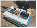
The discussion revolves around powering multiple devices in a low-voltage DC circuit, specifically for a shutter-speed testing device. Participants explore how to supply different voltage requirements from a single DC source, addressing theoretical and practical aspects of circuit design.

Discussion Character

  • Exploratory
  • Technical explanation
  • Debate/contested
  • Mathematical reasoning

Main Points Raised

  • One participant inquires about powering multiple devices with slightly different voltage requirements from a single DC source, emphasizing that no device requires more than 5 volts DC.
  • Another participant suggests that devices with different voltage requirements typically need separate power supplies, but acknowledges that "slightly different" voltages might be acceptable.
  • It is proposed that Low Dropout Regulators (LDOs) can be used to derive lower voltages from a higher DC source, with a caution about their power requirements and the need for heatsinks.
  • A participant mentions that linear regulators can also be used for this purpose, noting their suitability for low power applications.
  • There is a discussion about the differences between LDOs and standard linear regulators, highlighting cost, voltage drop, and stability requirements.
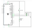
  • One participant shares specific voltage and current requirements for an LED and other components in the circuit, prompting further discussion on how to power them effectively.
  • Another participant suggests using a resistor to limit current for the LED instead of a regulator, provided the LED operates within a certain voltage range.
  • Questions arise about the overall design of the shutter-speed testing device, including the measurement method and the role of the OLED display.

Areas of Agreement / Disagreement

Participants express differing views on whether separate power supplies are necessary for devices with slightly different voltage requirements. While some suggest using LDOs or linear regulators, others propose simpler solutions like using resistors for LEDs. The discussion remains unresolved regarding the best approach for the specific circuit design.

Contextual Notes

Participants note the importance of understanding power requirements and the characteristics of components like LDOs and linear regulators. There is also mention of potential limitations related to power dissipation and the need for heatsinks.

Who May Find This Useful

This discussion may be useful for electronics enthusiasts, hobbyists working on low-voltage DC circuits, and those interested in power supply design for devices with varying voltage needs.

Birck
Messages
9
Reaction score
3
Hello, I'm putting together a shutter-speed testing device. I have the schematic at hand, but my question is this: If I need to power two or three different devices in a DC circuit, each with low, but slightly different voltage requirements, can I do that by using a single powerful enough DC source? If so, how do I separate out the outputs? By "low-voltage" I mean that nothing in the overall circuit requires more than 5 volts DC.
 
Engineering news on Phys.org
Normally devices with different, incompatible, voltage requirements will require separate power supplies. OTOH, "slightly different" might be slightly OK. For each device you must supply power within the specified limits. There are lots of different PS configurations to choose from. Without more information this is likely the best answer you are going to get. The answer to this sort of design problem ALWAYS begins with research. Get and read all of the datasheets, that is what EEs do first.
 
  • Like
Likes   Reactions: russ_watters and Bystander
Birck said:
how do I separate out the outputs?
There is an electric component called 'LDO' (or their equivalents) for this. Their input is a higher DC voltage, and they produce a lower one from it.
You need to be aware of the power requirements, because LDOs often require a heatsink.

It's common to have multiple LDOs (producing different voltages) on a single DC source.
 
Thank you for the information. I will gather all the power requirements and get that info back to the forum.
 
DaveE said:
Normally devices with different, incompatible, voltage requirements will require separate power supplies. OTOH, "slightly different" might be slightly OK. For each device you must supply power within the specified limits. There are lots of different PS configurations to choose from. Without more information this is likely the best answer you are going to get. The answer to this sort of design problem ALWAYS begins with research. Get and read all of the datasheets, that is what EEs do first.
Right. I need to get the specific power requirements together.
 
I did some digging and found that I can probably get along without divvying up the supply voltage-the circuit I've been modeling mine on is based on an Arduino Mini, which has its own USB connector, and stays within the limits of USB power. The only other power required is for an LED (2.5volts?), and can be supplied by battery or by a single low-voltage source, which I can come up with. But thanks for pointing out the LDO. I'll find out what I can about them.
 
Birck said:
The only other power required is for an LED (2.5volts?)
LEDs has their own tricks. They do have a 'voltage' (depending on current) but they require current, not voltage.

Try to check up on their usage.
 
OK. Thanks for pointing that out.
 
You are correct. It's easy to forget about the "diode" part of "led". I'm learning.
 
  • Like
Likes   Reactions: Tom.G and Rive
  • #10
within the low DC voltage range there are many linear regulators available in transistor cases that you simply need to provide a heatsink.
by using these you can have say a 12v DC line supply various loads on that line that require smaller voltages.
As long as the power isn't big, because then the regulators would heat up really bad + they only come within a limited current range. But for logic applications their suitable I think
 
  • #11
Thanks for that detail. So now I have two possible ways to deliver smaller voltages to more than one device- an LDO and a linear regulator. Or are they one and the same? Whichever, I know I also need a substantial heatsink, which I would not have thought of. Thanks again.
 
  • #12
Birck said:
Thanks for that detail. So now I have two possible ways to deliver smaller voltages to more than one device- an LDO and a linear regulator. Or are they one and the same? Whichever, I know I also need a substantial heatsink, which I would not have thought of. Thanks again.
Their the same almost, just think of a linear regulator. As long as you don't have high powers they work just fine, for high power applications and DC current you would need a switched regulator but that is a whole different ballgame

Now I could even try to give you examples if you told the specific voltages and amperages you need for each of your devices?
 
  • #13
Birck said:
So now I have two possible ways to deliver smaller voltages to more than one device- an LDO and a linear regulator. Or are they one and the same?
They are both linear voltage regulators (in contrast to switching voltage regulators), but they have important differences that you need to keep in mind when choosing which to use:
  • Standard (non-LDO) linear regulators will generally be less expensive than LDOs for the same power rating
  • LDOs are generally only used when the input-to-output voltage across the regulator is small, say a volt or two
  • LDOs have some quirky requirements that you have to be careful of (they use different transistor topologies inside in order to accomplish the low-dropout feature): they often have a minimum output current in order to remain stable, and they often cannot drive much output capacitance (so you are limited in how much decoupling capacitance you can put on that output voltage rail)
https://www.analog.com/en/design-ce...damentals-of-ldo-design-and-applications.html
 
Last edited:
  • Like
Likes   Reactions: artis and DaveE
  • #14
The only specifics I have are for one LED, alone, which requires 2.5-3 volts @ 20 mA. Far as I can tell, the rest of the circuit consists of a USB connector, an Arduino Micro microcontroller board, and a 4-pin OLED, requiring 2.8-5Volts (amps not indicated). The board itself draws 40 mA @ 7-10V. Photos of the circuit in operation show no other power source than USB.
 

Attachments

  • Screenshot 2023-07-31 at 11.13.44 AM.png
    Screenshot 2023-07-31 at 11.13.44 AM.png
    53.2 KB · Views: 131
  • Semi-schematic.jpg
    Semi-schematic.jpg
    28.2 KB · Views: 124
  • #15
If all you need to power is an Arduino and a LED, then I suggest match the voltage to the arduino and put a resistor in series with the LED.
Unless your LED is used for some very specific purpose, it will shine just fine within a certain range of voltages that don't need a LDO linear regulator but can be perfectly fine with a simple resistor.
As long as it's one LED and about 20mA a resistor dropping a couple of volts is manageable I think.
 
  • Like
Likes   Reactions: DaveE
  • #16
Thanks for your help. I should be able to manage that.
 
  • #17
For those just starting in electronics, here are further details for that LED resistor.

{[(Supply Volts) - (LED Volts)] / (LED Current)} = Resistor_value_in_Ohms

Or: R <ohms> = <volts_to_drop> / <amps_drawn>

Cheers,
Tom
 
  • #18
Birck said:
I'm putting together a shutter-speed testing device.
Birck said:
The only specifics I have are for one LED, alone, which requires 2.5-3 volts @ 20 mA. Far as I can tell, the rest of the circuit consists of a USB connector, an Arduino Micro microcontroller board, and a 4-pin OLED, requiring 2.8-5Volts (amps not indicated).
Can you say more about how you are going to measure the shutter speed? In your picture I think I see one Green LED aimed into the lens of your SLR camera, but I don't see anything to pick up the reflected light from that LED to let you know when the shutter is open or closed. Also, are you going to put a white reflector at the film plane (assuming it's a film SLR) to reflect the light that you shine into the lens when the shutter is open?

What is the function of the OLED? I see it in your schematic, but not in your picture...

1690928693868.png
 
  • #19
I think the OLED should be the display
The green thing is the phototransistor, and there should be an additional light source behind the camera somewhere. I guess it's about measuring the time of illumination through the open (mechanical) camera => shutter speed

I've suggested LDOs because of the mention of low voltage (it's usually a tight squeeze to use anything else in an 5V system, at least at amateur/beginner level) but this setup so far indeed requires just a single resistor to set the current of the additional LED..
 
Last edited:

Similar threads

  • · Replies 3 ·
Replies
3
Views
2K
  • · Replies 32 ·
2
Replies
32
Views
2K
Replies
61
Views
10K
  • · Replies 7 ·
Replies
7
Views
4K
  • · Replies 8 ·
Replies
8
Views
3K
  • · Replies 10 ·
Replies
10
Views
2K
Replies
6
Views
4K
  • · Replies 15 ·
Replies
15
Views
3K
  • · Replies 9 ·
Replies
9
Views
4K
  • · Replies 10 ·
Replies
10
Views
4K