tracker890 Source h
- 90
- 11
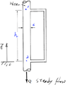
- Homework Statement
- To determine P2
- Relevant Equations
- hydrostatic pressure and energy conservation equation.
Please help me to understand which ans is correct.
 To determine the ##P2##.
$$
h_{LM}\ne 0
$$
Method 1:
$$dP=\frac{\partial P}{\partial x}dx+\frac{\partial P}{\partial y}dy+\frac{\partial P}{\partial z}dz$$$$\phantom{\rule{0ex}{0ex}}\rho \overset\rightharpoonup{a}=-\triangledown p+\rho \overset\rightharpoonup{g}\phantom{\rule{0ex}{0ex}}$$$$\triangledown P=\rho (\overset\rightharpoonup{g}-\overset\rightharpoonup{a})$$$$\because steady flow \therefore \overset\rightharpoonup{a}=0$$$$\therefore \triangledown P=\rho \left(\overset\rightharpoonup{g}\right)$$$$\therefore\triangledown P=\rho\left(\overset\rightharpoonup g\right)=\left\langle0,0,-g\right\rangle=\frac{\partial P}{\partial x}dx+\frac{\partial P}{\partial y}dy+\frac{\partial P}{\partial z}dz$$$$dp=-\rho gdz=-\gamma _wdz$$
$$P2=P1+\gamma _wh...........\left( ans1 \right)$$
$$////////////////////////////////////$$
Mtheod 2:
Energy Conservation Equation.$$\frac{{P}_{1}}{\gamma }+\frac{{{V}_{1}}^{2}}{2g}+{Z}_{1}=\frac{{P}_{2}}{\gamma }+\frac{{{V}_{2}}^{2}}{2g}+{Z}_{2}+{h}_{LM}$$$$
Q=AV_1=AV_2\
$$
$$
\therefore V_1=V_2
$$
$$
\therefore \frac{P_1}{\gamma _w}+Z_1=\frac{P_2}{\gamma _w}+Z_2+h_{LM}
$$
$$
\frac{P_2}{\gamma _w}=\frac{P_1}{\gamma _w}+Z_1-Z_2-h_{LM}
$$
$$
P_2=P_1+\gamma _w\left( Z_1-Z_2 \right) -\gamma _w\left( h_{LM} \right)
$$
$$
\ \ =P_1+\gamma _w\left( h \right) -\gamma _w\left( h_{LM} \right) ................\text{(ans2)}
$$
$$
h_{LM}\ne 0
$$
Method 1:
$$dP=\frac{\partial P}{\partial x}dx+\frac{\partial P}{\partial y}dy+\frac{\partial P}{\partial z}dz$$$$\phantom{\rule{0ex}{0ex}}\rho \overset\rightharpoonup{a}=-\triangledown p+\rho \overset\rightharpoonup{g}\phantom{\rule{0ex}{0ex}}$$$$\triangledown P=\rho (\overset\rightharpoonup{g}-\overset\rightharpoonup{a})$$$$\because steady flow \therefore \overset\rightharpoonup{a}=0$$$$\therefore \triangledown P=\rho \left(\overset\rightharpoonup{g}\right)$$$$\therefore\triangledown P=\rho\left(\overset\rightharpoonup g\right)=\left\langle0,0,-g\right\rangle=\frac{\partial P}{\partial x}dx+\frac{\partial P}{\partial y}dy+\frac{\partial P}{\partial z}dz$$$$dp=-\rho gdz=-\gamma _wdz$$
$$P2=P1+\gamma _wh...........\left( ans1 \right)$$
$$////////////////////////////////////$$
Mtheod 2:
Energy Conservation Equation.$$\frac{{P}_{1}}{\gamma }+\frac{{{V}_{1}}^{2}}{2g}+{Z}_{1}=\frac{{P}_{2}}{\gamma }+\frac{{{V}_{2}}^{2}}{2g}+{Z}_{2}+{h}_{LM}$$$$
Q=AV_1=AV_2\
$$
$$
\therefore V_1=V_2
$$
$$
\therefore \frac{P_1}{\gamma _w}+Z_1=\frac{P_2}{\gamma _w}+Z_2+h_{LM}
$$
$$
\frac{P_2}{\gamma _w}=\frac{P_1}{\gamma _w}+Z_1-Z_2-h_{LM}
$$
$$
P_2=P_1+\gamma _w\left( Z_1-Z_2 \right) -\gamma _w\left( h_{LM} \right)
$$
$$
\ \ =P_1+\gamma _w\left( h \right) -\gamma _w\left( h_{LM} \right) ................\text{(ans2)}
$$
Attachments
Last edited: