Shunt Resistor, Grain Boundaries & Solar Cell Circuit

Join the discussion
Ask a follow-up here, or get your own question answered by working scientists, mathematicians and engineers — people, not an autocomplete.
Real named experts · corrections over time · the nuance an AI answer skips
4 replies · 2K views
cemtu
Messages
99
Reaction score
7
Homework Statement
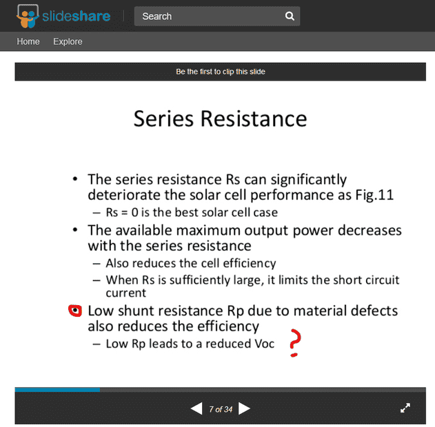
Why does the value of shunt resistor need to be very high for solar cell's efficiency?
Relevant Equations
none
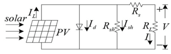
In the circuit equivalent of a solar cell, shunt resistor is described as "The irregular polycrystalline lattice grain boundaries that resist to the flow of electrical current in the silicon material."
If this explanation is correct, shouldn't it be "lower shunt resistance increases the current flowing".
However, the shunt resistor is connected in parallel to diodes. That means "higher the shunt resistor better the current output".
How and why so? I thought not having many grain boundaries is what makes the monocrystalline cells more efficient than polycrystalline solar cells?!
FScLx.png

https://www.scirp.org/html/7-6401007/fe85a7b6-645d-4341-8f35-dde69e519017.jpg
80ugh.png
 
Last edited:
Physics news on Phys.org
The better term is "Shunt Resistance" (as shown in the screenshot that you posted), not shunt resistor. You don't add a shunt resistor to a PV panel for some application reason.

Shunt resistance for any power source is bad. It shunts current from the power source through a resistance, which wastes some of the source power in heat generated in that shunt resistance.

So in PV cell design, you want to minimize any shunt paths for the generated photocurrent. Does that make sense?
 
berkeman said:
The better term is "Shunt Resistance" (as shown in the screenshot that you posted), not shunt resistor. You don't add a shunt resistor to a PV panel for some application reason.

Shunt resistance for any power source is bad. It shunts current from the power source through a resistance, which wastes some of the source power in heat generated in that shunt resistance.

So in PV cell design, you want to minimize any shunt paths for the generated photocurrent. Does that make sense?
Screenshot 2021-06-13 071745.png

Screenshot 2021-06-13 072013.png
 
berkeman said:
The better term is "Shunt Resistance" (as shown in the screenshot that you posted), not shunt resistor. You don't add a shunt resistor to a PV panel for some application reason.

Shunt resistance for any power source is bad. It shunts current from the power source through a resistance, which wastes some of the source power in heat generated in that shunt resistance.

So in PV cell design, you want to minimize any shunt paths for the generated photocurrent. Does that make sense?
As I understand it, the shunt resistance means that higher the polycrystalline lattice irregularity and many grain boundaries. This means higher current resistance and thus less current output, so efficiency of solar cell decreases. However, in the circuit model of a solar cell, a shunt resistor is connected in parallel to the diode and they say that it must have infinite resistance for the highest current output because it is in parallel. However infinite grain boundary irregularity means that there is infinite resistance to the whole current in the solar cell so no current flowing is produced.

There is a conflict here...