Sign hanging from massless beam attached to hinge supported by string

AI Thread Summary
The discussion focuses on the challenges of analyzing a sign hanging from a massless beam supported by a hinge and string, particularly regarding torque and force components. Participants emphasize the need for clearer diagrams, suggesting that images should be larger and upright for better readability. There is confusion over variable assignments in the free body diagram, with multiple forces labeled as T and F, which complicates the analysis. It's noted that the weight of the sign should be treated as acting at its center rather than split between two points of contact. Clear, typed equations in LaTeX are recommended for better communication of the calculations involved.
hisiks
Messages
6
Reaction score
0
Homework Statement
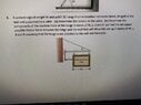
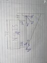
A uniform sign of weight W and width 2L hangs from a massless horizontal beam, hinged at the
wall and supported by a cable. (a) Determine the tension in the cable. (b) Determine the
components of the reaction force at the hinge in terms of W, L, d and ϴ (c) Find the minimum
possible friction force between the hinge and the wall that will allow this set-up in terms of W, L,
d and ϴ assuming that the hinge is not attached to the wall mechanically
Relevant Equations
Sum of Torques = 0
Sum of Forces = 0
Trig Equations
F=ma
Torque = Fdcos theta
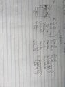
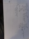
Attempted creating equations for zeros of torque and components of forces in x and y as seen in picture. Got lost with having only variables and the d & 2L for the length of the beam. Not sure how to do the question with two points of contact between the beam and the sign. Is the center center of mass changed because of that and/or what's the distance I use for that part?
 

Attachments

  • 74A362C4-6D5C-4092-88FD-76002827F4E3.jpeg
    74A362C4-6D5C-4092-88FD-76002827F4E3.jpeg
    68.7 KB · Views: 190
  • EDC8B2E0-1866-4C43-9DD5-E9DFEF3F161D.jpeg
    EDC8B2E0-1866-4C43-9DD5-E9DFEF3F161D.jpeg
    38.5 KB · Views: 139
Physics news on Phys.org
Your diagram is too small to be able to read the details. If I expand it it just gets fuzzy. Make the original half a page and don’t try to cram working into the same image.

Per forum rules, working should be typed in, preferably in LaTeX, not in an image. That makes it easier to refer to specific equations when making comments. Very clear writing and numbered equations is just acceptable, but your handwriting does nor qualify. Mine wouldn't either. I really cannot read it well enough to relate the variables to the diagram.

And do try to ensure the images are upright!

When writing moments equations, always state the axis.
 
haruspex said:
Your diagram is too small to be able to read the details. If I expand it it just gets fuzzy. Make the original half a page and don’t try to cram working into the same image.

Per forum rules, working should be typed in, preferably in LaTeX, not in an image. That makes it easier to refer to specific equations when making comments. Very clear writing and numbered equations is just acceptable, but your handwriting does nor qualify. Mine wouldn't either. I really cannot read it well enough to relate the variables to the diagram.

And do try to ensure the images are upright!

When writing moments equations, always state the axis.
Understandable, that was just my quickly written first attempt, here's a clearer process.
 
hisiks said:
Understandable, that was just my quickly written first attempt, here's a clearer process.
 

Attachments

  • 49320BFC-14FC-4AB7-AC6E-D456AD1F8E9E.jpeg
    49320BFC-14FC-4AB7-AC6E-D456AD1F8E9E.jpeg
    26.4 KB · Views: 130
  • 3D665438-1AA5-4FFE-A515-9448C163BB26.jpeg
    3D665438-1AA5-4FFE-A515-9448C163BB26.jpeg
    34.6 KB · Views: 137
Your diagrams are sideways
 
erobz said:
Your diagrams are sideways
... again
 
hisiks said:
Understandable, that was just my quickly written first attempt, here's a clearer process.
You have two versions of the torque the sign's weight exerts on the hinge, one with Wd, one with ##W\frac{d+2L}2##.
They're both wrong.

(When I said to number all equations, if you won't type them, I meant all.)
 
20221127.jpg


20221127b.jpeg


20221127a.jpg
 
You have 3 things labelled T on the diagram. My red pencil would strike instantly.
 
  • #10
Welcome, @hisiks !

Regarding your free body diagram (FBD):
You have assigned the variable T to three different forces.
You have assigned the variable F to the reaction forces at the pivot, which are normally identified as R.
Tx and Ty are understood as forces; therefore, it results confusing to see FTx and FTy in your equations.

You don't need to split the weight of the sign in two, for the moment induced by the weight, the application distance of that force is at the center point of the sign, regardless of how it hangs from the bar.
Please, try the FBD and associate equations again.
 
  • #11
Also, it is a good habit to cross out any vector that you resolve into components, e.g. FH, to avoid double-counting or else just draw the two components.

Also your equation (4) is an identity and says T = T, nothing new.
 
  • Like
Likes hutchphd and Lnewqban
Back
Top