Simulating this cascoded NMOS logic circuit

  • Topic: Engineering 
  • Thread starter Thread starter elektro2021
  • Start date Start date
  • Tags Tags
    Circuit Logic
Join the discussion
Registration is free. Start your own thread to ask a follow-up.
14 replies · 3K views · last reply
elektro2021
Messages
6
Reaction score
0
New poster has been reminded to always show their work when starting schoolwork threads
Homework Statement
Size and simulate the circuit (IMAGE BELOW) so that it achieves a 100 ps delay (50-50) using 0.25 μm devices, while driving a 100 fF load on both differential outputs. (VDD = 2.5V) Assume A, B and their complements are available as inputs.
Relevant Equations
vailable common data for nmos are following Vt=0.43(V),Vdsat=0.63(V),k'=115x10^-6 (A/V^2),lambda=0.06(v^-1)
I need help for following exercise from Rabaey - Digital Integrated Circuits: A Design Perspective

Size and simulate the circuit (IMAGE BELOW) so that it achieves a 100 ps delay (50-50) using 0.25 μm devices, while driving a 100 fF load on both differential outputs. (VDD = 2.5V) Assume A, B and their complements are available as inputs.
Available common data for nmos are following Vt=0.43(V),Vdsat=0.63(V),k'=115x10^-6 (A/V^2),lambda=0.06(v^-1)
Please help me.
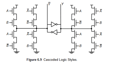
Circuit schematic of cascoded logic styles: two NMOS pull-down stacks on each side, with inputs A, B, A-bar and B-bar, driving a cross-coupled inverter pair producing outputs Y-bar and Y. Caption: Figure 6.9 Cascoded Logic Styles.
 
Physics news on Phys.org
Welcome to PF.
Have you yet identified the two input logic function with a complementary output ?
How will you simulate the gate and delay ?
 
Welcome to PF. :smile:

You need to show some effort before we can provide tutorial help. Please show us how you will approach this question.

Also, I'm a little confused by this symbol in the middle of your NMOS logic circuit -- what is it meant to represent? Is it some IP that is defined elsewhere in the problem statement?

Circuit schematic of two inverter symbols stacked vertically, each with an input on the left and an output on the right, with the top inverter's output wired to the bottom inverter's input and a connection at the right.
 
berkeman said:
Also, I'm a little confused by this symbol in the middle of your NMOS logic circuit
It is a memory element made from two soft output inverters.
It retains the last valid state of the gate, so prevents floating inputs consuming current.
 
  • Informative
Likes   Reactions: berkeman
Baluncore said:
Welcome to PF.
Have you yet identified the two input logic function with a complementary output ?
How will you simulate the gate and delay ?
I think it's a XOR port for Y and XNOR for Y negate.I don't want to simulate the circuit by a simulator but I want to size (by hand) W/L for NMOS transistors to get a 100 ps delay (50-50) using 0.25 μm devices, while driving a 100 fF load on both differential outputs.
 
elektro2021 said:
I don't want to simulate the circuit by a simulator but I want to size (by hand) W/L for NMOS transistors to get a 100 ps delay (50-50) using 0.25 μm devices, while driving a 100 fF load on both differential outputs.
Okay, can you show us how you are going to approach that?
 
elektro2021 said:
I want to size (by hand)
Have you attempted to do that yet?
 
I think that I need to compute current charge/discharge for 100 fF capacitor...what do you think?
 
I think that Ic=C*(dv/dt) con C=100 fF and dv/dt= (VDD/2)/T con T=100ps and VDD=2.5V...what do you think?
 
So after you determine the voltages and currents involved, how will you choose the aspect ratio for your geometry?

elektro2021 said:
I want to size (by hand) W/L for NMOS transistors to get a 100 ps delay (50-50) using 0.25 μm devices
 
I don't know...I think that NMOS current depends by W/L...please help me
 
We *are* trying to help. What do your class notes say about aspect ratio effects on voltages and currents?