Symmetrical component example: can't understand solution

Click For Summary
SUMMARY

This discussion focuses on the calculation of symmetrical components, specifically the zero sequence circuit from Stevenson's Power System Analysis book, examples 6.1 and 11.9. The user seeks clarification on the per unit (pu) reactance of transformers T1 and T2. The correct method for T1 involves changing bases using the formula Xpu=OLDpu x OLDbase/NEWbase, while T2's reactance is calculated by reflecting impedances based on its own ratings. The MVA ratings and voltage levels play a crucial role in these calculations.

PREREQUISITES
  • Understanding of symmetrical components in power systems
  • Familiarity with per unit (pu) system calculations
  • Knowledge of transformer ratings and impedance reflection
  • Basic concepts of power system analysis as outlined in Stevenson's book
NEXT STEPS
  • Study the concept of per unit system transformations in power systems
  • Learn about impedance reflection techniques for transformers
  • Review example problems in Stevenson's Power System Analysis, particularly examples 6.1 and 11.9
  • Explore the implications of MVA ratings on circuit calculations
USEFUL FOR

Electrical engineering students, power system analysts, and professionals involved in transformer design and analysis will benefit from this discussion.

ffp
Messages
96
Reaction score
5
Thread moved from the technical forums to the schoolwork forums
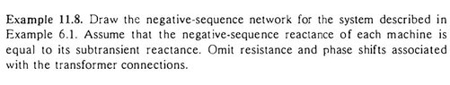
Ok, now I'm studying symmetrical components. Im using Stevenson's Power System Analysis book and example 11.9 asks for the zero sequence circuit of the example 6.1 in the same book.

Here's the example and the solution:
SmartSelect_20230123_225052_Moon+ Reader Pro.jpg

Here's example 6.1, so we can see what is the circuit:
SmartSelect_20230123_225223_Moon+ Reader Pro.jpg


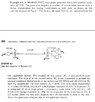
Here's the beginning of the solution, where I'm stuck...

SmartSelect_20230123_225443_Moon+ Reader Pro.jpg


I believe de X of T1 (0.0857 pu) is found by changing bases (Xpu=OLDpu x OLDbase/NEWbase). So 0.1 is the pu of T1, 300 is the Sbase (MVA) of the generator (and hence, system) and 350 is the Sbase (MVA) of T1. Is that right?

If so, why is X of T2 calculated differently, I believe by reflecting impedances? If that's really what he's doing, why is he using 13.2 and 13.8?

I'm really lost here with this example.
 

Attachments

  • SmartSelect_20230123_225052_Moon+ Reader Pro.jpg
    SmartSelect_20230123_225052_Moon+ Reader Pro.jpg
    21.1 KB · Views: 138
  • SmartSelect_20230123_225223_Moon+ Reader Pro.jpg
    SmartSelect_20230123_225223_Moon+ Reader Pro.jpg
    52 KB · Views: 119
Physics news on Phys.org
ffp said:
I believe de X of T1 (0.0857 pu) is found by changing bases (Xpu=OLDpu x OLDbase/NEWbase). So 0.1 is the pu of T1, 300 is the Sbase (MVA) of the generator (and hence, system) and 350 is the Sbase (MVA) of T1. Is that right?
Yes. Both T1 and the generator have the same voltage rating(and are at the same voltage level in the line diagram). This is why only the ratio of MVA ratings is used to find the new pu reactance.
ffp said:
If so, why is X of T2 calculated differently
The MVA rating of T2 is same as the base MVA (300MVA). The 0.1 pu reactance of T2 is w.r.t its own ratings (300MVA, 13.2kV). To convert it properly according to the motor citcuit voltage level, it is divided by the motor circuit voltage level (and then squared).
 

Similar threads

  • · Replies 12 ·
Replies
12
Views
926
  • · Replies 5 ·
Replies
5
Views
2K
  • · Replies 2 ·
Replies
2
Views
2K
  • · Replies 10 ·
Replies
10
Views
4K
Replies
27
Views
4K
Replies
2
Views
712
  • · Replies 3 ·
Replies
3
Views
5K
Replies
3
Views
3K
  • · Replies 61 ·
3
Replies
61
Views
9K