Testing if a multiplier is doubling frequency

  • Thread starter Thread starter r19ecua
  • Start date Start date
  • Tags Tags
    Frequency Testing
Join the discussion
Registration is free. Start your own thread to ask a follow-up.
15 replies · 5K views · last reply
r19ecua
Messages
17
Reaction score
0
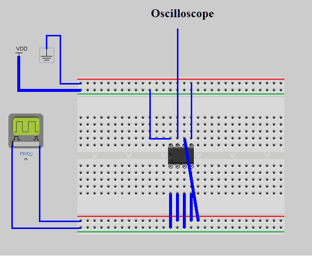
Here is my circuit
Breadboard circuit diagram with a VDD supply and ground symbol at top left, a square-wave function generator labelled FREQ at left, a chip on the breadboard, and wires running to a probe labelled Oscilloscope.


I'm trying to double the frequency of my input to my output.

k = 1/10 V

For example: input is VmSin(2[itex]\pi[/itex]1000t)/10
Vo = (VmSin(2[itex]\pi[/itex]1000t))^2/10
Output should be Vm^2/20 + Vm^2cos(2[itex]\pi[/itex]2000t)/20

My oscilloscope isn't picking up on the doubling, so I know my circuit is incorrect. May I have assistance? The ultimate goal, is to develop a phase detector.
Circuit I'm trying to create:
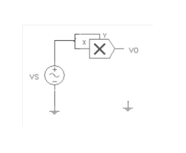
Circuit schematic of a sinusoidal source VS with its negative terminal grounded, connected to the X input of a multiplier block with Y input tied to X, output labelled VO.
 
Last edited:
Engineering news on Phys.org
And ... what is the chip ??

giving ALL the info helps people help you :)

Dave
 
Apologies! I'm using an AD633 with Vs = +15V and -VS = -15V.. X2 = Y2 = Z = 0

Here is the data sheet:
Block diagram of the AD633JN/AD633AN analog multiplier IC, showing inputs X1, X2, Y1, Y2 and Z, a summing stage, output W, and supply pins +VS and -VS.
 
r19ecua said:
Apologies! I'm using an AD633 with Vs = +15V and -VS = -15V.. X2 = Y2 = Z = 0

Here is the data sheet:
Functional block diagram of the AD633JN/AD633AN analog multiplier IC, showing inputs X1, X2, Y1, Y2, a 1/10V scaling block, a summing node, an amplifier A, output W, input Z and supply pins +VS and -VS.

Your picture does not show +/- 15V rails. It shows a positive rail and ground for powering the IC.

And when you correct that, is your signal generator ground the same as the power supply ground? What amplitude and frequency are your sig gen set for?
 
And when you say "My oscilloscope isn't picking up on the doubling", what does the output look like?
 
berkeman said:
Your picture does not show +/- 15V rails. It shows a positive rail and ground for powering the IC.

And when you correct that, is your signal generator ground the same as the power supply ground? What amplitude and frequency are your sig gen set for?

That's what I wanted to make sure of! In order to meet the +/- 15V rail requirement, I'd need a +15V rail and a - 15V rail, yes? So 2 different sources and a separate rail for ground, but I did this and my frequency is not doubled. I had used a red lead for both Vs inputs (+/-) and grounded the negative leads on another rail.

My amplitude(Vm) is 10V and my frequency is 1000Hz.

Here is my waveform:
Oscilloscope screen with two traces: yellow CH1 is a sine wave, and blue CH2 is a rectified waveform with peaks and sharp drops, with readings Vpp 10.00V and 3.28V and frequencies 1.01KHz and 1.00KHz.
 
Last edited:
@r19ecua
Is there a problem for you to give us a proper schematic diagram of the exact circuit you are (or think you are) using? Either the chip is broken or you have connected it wrongly and a schematic could help people find what's wrong. It's not too much to ask, is it? You should already have drawn yourself one, in any case.
 
My first post is the circuitry I was rolling with, the schematic followed soon after.. The VDD is suppose to be the Vs 15V and the ground rail is coming from the negative terminal of the power supply. The problem? I just want to see the frequency doubled using a multiplier (AD633) with X2, Y2 and Z = 0 (grounded). The input frequency is Vm = 10Sin(2pi1000t)V

@berkeman
No, the ground for my function generator is not the same as the power supply ground. Should I make them the same? I was using some virtual breadboard software and it turns out it was a bust.
 
Last edited:
r19ecua said:
My first post is the circuitry I was rolling with, the schematic followed soon after.. The VDD is suppose to be the Vs 15V and the ground rail is coming from the negative terminal of the power supply. The problem? I just want to see the frequency doubled.

@berkeman
No, the ground for my function generator is not the same as the power supply ground. Should I make them the same? I was using some virtual breadboard software and it turns out it was a bust.

Now there's a lesson for you. :biggrin:
You can only believe what you draw on paper and analyse with your mind. Simulations are always to be treated with some suspicion if you don't 'test' them like you'd test a wired circuit. A dodgy bit of software is worse than a dodgy component because you can replace a component but the software will do the same daft thing again and again.
 
sophiecentaur said:
Now there's a lesson for you. :biggrin:
You can only believe what you draw on paper and analyse with your mind. Simulations are always to be treated with some suspicion if you don't 'test' them like you'd test a wired circuit. A dodgy bit of software is worse than a dodgy component because you can replace a component but the software will do the same daft thing again and again.

The waveform I posted is an actual test. I only drew up the circuit via simulation software just so you all could see what I put together. If I were to simulate the schematic on multisim, the frequency doubles. When I put it into practice (by building it the way I initially posted), my results are the waveform I posted. The 2 Vs inputs of the AD633 are receiving +15V (the + & - inputs of the IC).
 
Last edited:
You have 15 V from +Vs to -Vs. The AD633 datasheet lists a minimum of ±8 V, i.e. you should have 16 V from +Vs to -Vs at minimum. It might work at 15 V but you'll have no guarantee that it'll be within the specifications listed in the datasheet.

For 20 V from +Vs to -Vs, your inputs should be between 4 V and 16 V relative to -Vs (have a look at figure 6 in the datasheet).

Edit:
Did you use a single-ended probe:
Black oscilloscope probe with a BNC connector at one end, a long coaxial cable, a sprung ground alligator clip on a short lead, and a pointed probe tip with a slide switch on the barrel.


when you recorded the waveforms you posted in #7? Where did you attach the ground clip?
 
Last edited:
OK, this is my actual circuit:
Photo of a breadboard circuit with red and green jumper wires, alligator clips labelled Vs +15V (S1), Vs -15V (S2), 15V (S2) Grounded, -15V (S1) Ground, Output (CH2), CH1 and Freq Generator, and labels X1, X2, Y2, Z and V1.


I have 2 different sources putting out 15V. If you refer to the datasheet there are two inputs.. a VS+ and a VS-. In the picture, I have for both inputs, a +15V going through them. The negative terminal of these two inputs are placed on the same rail and are grounded. X2 = Y2 = Z = 0, these inputs were grounded as well.

My initial guess was to put a +15V(1st source) through the +Vs input(pin 8) on the IC and a -15V (from the second source) on the -Vs input(pin 5) of the IC. The -15V (from 1st source) would be ground and the +15V(from second source) would be grounded as well. X2 = Y2 = Z = 0, these inputs were grounded as well.

Edit: If you refer to the datasheet above, w is my output.
 
Last edited:
I won't have a chance to look it through until later, but could you try disconnecting the +15 V and -15 V clips and measure the voltage between them with a multimeter?
 
OK, I finally have the frequency being doubled. I didn't draw it, but the clip for my function generator is grounded... This is the circuit I constructed:
Circuit schematic of a multiplier with a function generator feeding inputs X1, X2, Y1 and Y2, supplies Vs+ and Vs- from PSU 1 and PSU 2 at 15V, and an output terminal labelled Output.


my output waveform:
Oscilloscope screenshot with two traces: yellow CH1 sine wave at 1.01 kHz, Vpp 10.00 V, and teal CH2 rectified-looking wave with twice as many peaks, at 2.02 kHz. Timebase 250 µs/div.

The frequency for my output (CH2) continues to fluctuate between 1 ~ 2kHz. The result is also smaller than expected. Input voltage is 10V as seen by the 5 volts / div. While the output voltage is at 1 volt/div and barely passes 3V. Output was expected to be 5V based on the formula
Vo(t) = Vs(t)^2/10
Vs(t) = 10sin(2pi1000t)
Vo(t) = 5 - 5cos(2pi1000t)V (estimated)

@milesyoung
DMM measures 30V
 
Last edited:
Your input signal is:
Vin = A*sin(ω*t), A = 5 V, ω = 2*pi*1000 rad/s

Your output signal should be:
Vout = Vin2/(10 V) = (A*sin(ω*t))2/(10 V) = A2/(10 V)*sin2(ω*t) = A2/(10 V)*( (1 - cos(2*ω*t))/2 ) =
A2/(20 V)*(1 - cos(2*ω*t))

The DC offset and amplitude of the AC component at the output should be (5 V)2/(20 V) = 1.25 V, which seems about right for the output you've measured.

I can only recommend that you:
- Bond together the ground of the signal generator and both supplies at a common point so you won't have the noise between them added to the AD633 input signal.
- Move the probe and ground clip as close as possible to the pins for measurements.
- Consider adding some decoupling caps to the AD633 supply pins (as close as possible) as shown in the datasheet.