Three Phase Wye Delta Transformer Feeding Single Phase Load

7 replies · 4K views · last reply
BuzzBar
Messages
3
Reaction score
2
Three wye-delta (120:480) is feeding single phase load as per diagram. How will current be distributed in the delta winding when single phase is connected between line A and B ?

When I solve by hand I get different results when simulating in Multisim.
Hand calculation - Winding A will be in parallel with winding B&C (which are in series and B+C=-A). This will cause the current to be split evenly between windings A (50A) and B&C (50A).

However when I use Multisim currents are winding A (66A) and B&C(33A).
Which calculation is correct? I don't understand how Multsim is solving winding A to carry double the current in winding B&C,

Circuit schematic of a three-phase wye-to-delta transformer bank with sources V1, V2 and V3 at 120Vrms, 60Hz, phase angles 0, -120 and 120 degrees, feeding a 4.8 ohm load R3 through transformers T1, T2 and T3, with line numbers 1 to 12 and small resistors R1 and R2 of 0.001 ohms.


Multisim schematic of a three-phase wye-delta transformer bank feeding a single-phase load, with overlaid current and voltage meter readouts on each winding and at the load.
 
Last edited by a moderator:
Welcome to PF.

Is this for schoolwork? If so, I can move it to the schoolwork forums for you. Also, can you clarify on your diagram which are "line" A/B/C and "winding" A/B/C? Thanks.
 
I haven't actually tried to solve this yet, IDK, maybe later. But I suspect that you might be adding up the currents algebraically, without regard to their phase difference. In fact, they will add like vectors with 120o angles. The problem is well defined with that "phasor" provision. Frankly, it's just a book keeping exercise of KVL/KCL with out of phase sinusoids.

Please let us know what confuses you about the analysis by hand. Write out the equations of the voltages and currents in the secondary circuit (I know, it is a PITA, that's why I haven't done it for you, yet, LOL). Sorry if I'm not giving you credit for knowing about vectors/phasors in circuits. Often there is a bit of guessing required about the OP's background knowledge.
 
berkeman said:
Welcome to PF.

Is this for schoolwork? If so, I can move it to the schoolwork forums for you. Also, can you clarify on your diagram which are "line" A/B/C and "winding" A/B/C? Thanks.
Hi, yes its is for school. I added line and winding currents designation to the diagram.

Circuit schematic of three single-phase transformers T1, T2 and T3 in a delta-wye arrangement, with 120Vrms 60Hz sources V1, V2 and V3 at 0, -120 and 120 degrees, and a 4.8 ohm load R3 across terminals A and B.
 
Last edited by a moderator:
DaveE said:
I haven't actually tried to solve this yet, IDK, maybe later. But I suspect that you might be adding up the currents algebraically, without regard to their phase difference. In fact, they will add like vectors with 120o angles. The problem is well defined with that "phasor" provision. Frankly, it's just a book keeping exercise of KVL/KCL with out of phase sinusoids.

Please let us know what confuses you about the analysis by hand. Write out the equations of the voltages and currents in the secondary circuit (I know, it is a PITA, that's why I haven't done it for you, yet, LOL). Sorry if I'm not giving you credit for knowing about vectors/phasors in circuits. Often there is a bit of guessing required about the OP's background knowledge.
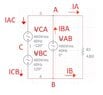
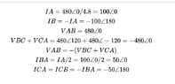
Hi, I rearranged the delta circuit and treat each winding as as voltage source. I use VAB for reference and consider it to be at angle 0. When I add VBC and VCA as vector sum I get them to be equal to -VAB. So from this I have two equal voltage sources, so current should be dived equally between two voltage source branches,
 
Attachments
  • Circuit schematic of a delta-connected three-phase source with nodes A, B and C feeding R3 = 4.8Ω between A and B; three 480Vrms 60Hz sources labelled VCA (-120°), VAB (0°) and VBC (120°), with branch currents IAC, IBA, ICB, IA, IB marked.
    Capture2.JPG
    17.1 KB · Views: 115
  • Handwritten-style equations in LaTeX on a white background: IA = 480∠0/4.8 = 100∠0, IB = -IA = -100∠180, VAB = 480∠0, VBC + VCA = 480∠120 + 480∠-120 = -480∠0, VAB = -(VBC + VCA), IBA = IA/2 = 100∠0/2 = 50∠0, ICA = ICB = -IBA = -50∠180.
    Capture3.JPG
    21.6 KB · Views: 115
The circuit is overdefined by having three voltage sources, with a closed delta that must sum to zero. Something must give.

The voltage of the delta secondary, relative to ground is floating, unspecified.
 
You have two voltage sources across a single load. One has double the source impedance of the other unless otherwise defined. It should be clear after stating that assumption.
 
It is obvious that Multisim has used the equation ## I_{AC}+I_{CB}+ I_{BA} = 0A ## instead of ## I_{BA} = \frac{I_{A}}{2} ## has been used by @BuzzBar.
The system is unbalanced and in my opinion the Multisim approach is wrong.