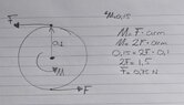
Torque due to moment of inertia (?)

AI Thread Summary
To calculate the torque needed to rotate a 7.5 kg disk with a radius of 100 mm, the moment of inertia must be considered, which is influenced by the weight distribution and friction in the system. If the bearings are frictionless, any torque will initiate rotation, but friction will require additional torque to overcome static resistance. The discussion highlights the importance of measuring bearing friction and selecting appropriate bearings for the load. Calculations provided indicate that static friction and the torque from connecting rods must be factored into the total torque required for the motor. Understanding these dynamics is crucial for selecting a suitable motor for the application.
Mech_LS24
Messages
148
Reaction score
16
TL;DR Summary
Just a want to have an indication how much torque I need for rotating a plateau with 7.5 kg. See sketch for clearer view.
Hi!

I would like to calculate (roughly) how much torque is needed bringing the blue plateau in movement. Assume the blue plateau is loaded with 7.5 kg. The radius of the blue circle is 100 mm.

1626097074669.png
 
Engineering news on Phys.org
Any amount of torque would rotate the disk. So you should set some goal of quantity.
 
  • Like
Likes Mech_LS24
Thanks for your reply @anuttarasammyak .

Not any amount would rotate the disk, the disk is loaded with a weight of 7.5 kg. This would give the disk a sort of moment of inertia isn't is? Or do I miss the mark here?

NB. the load is applied in the Z-direction, so actually 'into' the screen.
 
Mech_LS24 said:
Not any amount would rotate the disk, the disk is loaded with a weight of 7.5 kg. This would give the disk a sort of moment of inertia isn't is? Or do I miss the mark here?
If the bearings are frictionless, then the rotation will happen with any torque, just more slowly for higher moments of inertia. The relevant equation is ##\tau = I \alpha##

However, if there is bearing friction, you need to overcome the static bearing friction to start the disk rotating. Have you measured the friction of the loaded bearings? Are you using the right type of bearings for the way you are loading the axle?
 
  • Like
  • Informative
Likes crudux_cruo, Lnewqban and Mech_LS24
Does the plate rest on a friction free mechanical bearing that keeps it centred ?
or does it rest with friction, like on a bed of sand ?
 
berkeman said:
If the bearings are frictionless, then the rotation will happen with any torque, just more slowly for higher moments of inertia. The relevant equation is
If I take an angular acceleration of 3 rad/s^2, the torque needed is:
I= 0.5m*r^2 = 0.5*7.5*100^2 = 50000 kg*mm^2
α = 3 rad/s^2

τ= I*α = 0.05 (kg*m^2) * 3 (rad/s^2) = 0.15 Nm

Ok, this is frictionless.
Can I calculate the angular acceleration to RPM? I can't imagine 3 rad/s^2 yet.

berkeman said:
However, if there is bearing friction, you need to overcome the static bearing friction to start the disk rotating. Have you measured the friction of the loaded bearings? Are you using the right type of bearings for the way you are loading the axle?
I have measured the friction of the bearings yet, this was just a concept. I wanted to know what amount of torque I roughly need for the motor. Maybe as a nice learning process for me I can calculate the static bearing friction for a plain bearing and angular contact bearings?

Using the following reference: Bearing friction coefficients
Angular contact bearings: .0020

Now calculate the torque:
1626156866161.png

P = 7.5kg * 10 = 75 N
μ= 0.0020
dm = 10 mm = 0.01 m (assumption)

Torque = (75N*0.002*0.01m)/2
Torque = 7.5*10^-4 Nm

Do I need to add the torque values for the total torque needed?
 
Baluncore said:
Does the plate rest on a friction free mechanical bearing that keeps it centred ?
or does it rest with friction, like on a bed of sand ?
Yep it does rest with friction. I have tried to calculate the friction in post #6. Hopefully on the correct way :)
 
Anyone who could support with post #6? Thanks
 
Mech_LS24 said:
Anyone who could support with post #6? Thanks
How many alternative situations are you considering? What is, or is not, friction free? What stops things moving sideways? Where are the bearings? What sort of bearings are used?

Just because you put numbers in an equation does not mean the equation is applicable to the situation you had in mind. You must describe the situation and ask the question clearly.

We are not mind readers and won't waste valuable time trying to guess what you do not tell us. Instead we just walk away to escape the confusion, and solve some clearly specified problem elsewhere.
 
  • #10
Thanks for your reply @Baluncore .

Just a want to have an indication how much torque I need for rotating a plateau with 7.5 kg
As mentioned in post #1 I want to have an indication for the needed torque. With this torque I assumed I could select a proper motor.

But (again) as former student and just graduate, I am at the beginning of learning 'new' things. I appreciate you mentioned me on that friction. But you can't expect any magic from me. I shouldn't open this topic if I already knew it. By asking: "does it rest with friction", I can not come with all the things needed for that, because I just doesn't be familiar with that yet.

Now let's try to figure out that friction. I will try to make some sketches and come back to you.
 
  • #11
Does this sketch helps?

Friction_disk.jpg
 
  • #12
I assume that by blue “plateau” you mean a plate, disk, or circle.
I assume that the small white circle marks the fixed centre of disk rotation.
What is the significance of the blue disk 100 mm radius specification?

I assume the black rectangle on the right hand side of the post #1 diagram is a bar that rotates about the fixed white circle.
I assume that the two grey lines are fixed length links that connect the circle to the bar.
I assume that the small red circles mark moving connection pins.
I observe that since the diameter of the blue circle is less than the length of the black bar, the system will be rigid and so cannot rotate.
What is the purpose of the black bar and two grey links?

How much does the blue disk (and shaft)? and outer ball race, and half the links weigh? When you say the blue disk is loaded with 7.5 kg, how is that load arranged and placed? I notice the added load has now risen to 10 kg. Notice that the moment of inertia is dependent on how the mass is distributed over the radius. But if you want to know the torque needed to break the friction then load distribution is not important.

The diameter of the ball centres in the bearing is needed from the data sheet.
What is the part number, 72XX, 73XX, of the angular contact ball bearing ?
 
  • #13
Thanks @Baluncore .

A description of the concept and hopefully it gives a more detailed view for your assumptions, as well I sketched the situation which is visualized below the description:

  • The blue plateau is as disk indeed, this disk carries the load
  • The white points are rotation pivots
  • I specified the radius of 100 mm for the disk, but haven't looked at details here. I can think of the amount of torque in the rods increase by a larger radius. So, if the radius increase, the forces in the rods decreases.
  • The black rectangle is an kind of a transmission for transfer the torque from the motor to the arm which brings the system into 'movement'
  • The red circles are pins which connects the rods from the disk to the motor and vice versa.
  • Good point mentioning the blue disk should be larger as the radius of the black bar. Changed that.
  • The disk is made for example from aluminium, the rods (arm) are most likely made of a steel. So I assume the weight of those parts are in total 1.5 kg. Added to the 10kg makes it 11.5 kg in total.
  • The load is probably loaded equally over the disk, I didn't find a nice way to draw that.
  • The bearing is an 7200 BECBP angular contact bearing. I am not a bearing experts so all recommendations are welcome :)
  • The bearing is locked with a bolt. A disk is pushed through the bolt into the fixed pin.

Please let me know if the description is understandable for you.

Motor_torque_calc_concept.jpg
 
  • #14
Without specifying the distribution of the mass we cannot compute inertia. As I understand it, you only want to know the force needed to initiate movement of the disk. You do not require the rate of disk acceleration.
You need the coefficient of static friction, but the coefficient of dynamic friction is usually specified. I think we must assume the coefficient of static friction will be about twice that specified for dynamic friction. https://en.wikipedia.org/wiki/Friction#Static_friction

The effective radius of the 7200 bearing is (d+D)/4 = 10 mm radius.

Only half the weight of the rods is carried by the 7200 bearing, the other end is carried by the motor bar. You need to itemise the materials list so as to proportionately allocate mass to load the motor bar or the disk.

Since the motor and bar must rotate before the disk, you will also need to know the motor bearing and drive train friction. The motor and bar will transmit a force to the disk through the two rods and four pins. Friction in those rod pin-joints will almost certainly be greater than friction in the 7200 bearing.
 
  • #15
I would like to know the size of motor is needed for a concept like this. Probably I have been at the beginning of this concept been too complacent.

Baluncore said:
The effective radius of the 7200 bearing is (d+D)/4 = 10 mm radius
What is the effective radius? The formula is based on? I got web hits with bolted joints when I search effective radius bearings o_O

Hmm okay regarding the materials list, I take this:
  • Disk: EN-AW6082, t= 5mm, d= 200mm, density = 2700 kg/m^3, weight = 0.42 kg
  • Motor Bar: POM-C, 100x30x8 (L*W*H), density = 1.41 g/cm^3, weight = 0.034 kg
  • Rod: 1.4301 (Stainless steel), d= 10 mm, length = 300 mm, density = 8 kg/m^3, weight = 0.19 kg
  • Bearing 7200 mass = 0.03 kg
Next...?
Static friction (Wikipedia):
{\displaystyle F_{\text{max}}=\mu _{\mathrm {s} }F_{\text{n}}}

Us = 0.75 (assuming steel on steel)
Fn = 100 N (load on the disk) + ((0.42+0.034+(0.19*2)+0.03)*9.81) = 108.5 N

Fmax = 0.75*108.5 = 81.4 N

Baluncore said:
Since the motor and bar must rotate before the disk, you will also need to know the motor bearing and drive train friction. The motor and bar will transmit a force to the disk through the two rods and four pins. Friction in those rod pin-joints will almost certainly be greater than friction in the 7200 bearing.
Shouldn't I first define the motor? Then check the specifications on motor bearing and drive train friction? The pin-joint will probably be with spherical plain bearings, I found the following formula on the SKF site:
M = 0,5 μ P dm
 
  • #16
Mech_LS24 said:
What is the effective radius? The formula is based on?
The inner and outer race thickness are close to equal. So; re = (d+D)/4; is the average of inner and outer diameters, converted to radius, which is the length of the torque arm.
Because mean diameter, dm = 2 * effective radius of the ball race.
M = 0,5 · μ · P · dm ; can be reduced to; M = μ · P · re.

Mech_LS24 said:
Shouldn't I first define the motor?
Specify the type of motor, and select an initial choice. Use the specifications to evaluate that choice in your application.
If you specify a DC servo motor, then the initial torque will be proportional to the initial current, which will simply be; motor voltage divided by motor resistance.
 
  • Like
Likes Mech_LS24
  • #17
Baluncore said:
The inner and outer race thickness are close to equal. So; re = (d+D)/4; is the average of inner and outer diameters, converted to radius, which is the length of the torque arm.
The term 'race' thickness isn't known by me, but I got the message (sketch below).
I was thinking about an TowerPro servo motor, I have used one in the past at school, because it was easy to program with Arduino. I think the motor isn't able to 'move' the load.

I am a bit confused now what I need to consider, the following is the case now(?):
  • Total mass that should be consider is 108.5 N (see Fn in post #15)
  • Bearing is a 7200 angular contact bearing
  • Re for 7200 bearing is 10mm
  • Static friction for the 7200 bearing is 81.4 N (see Fmax post #15)
  • Type of motor is a TowerPro servo motor
  • Output torque of the TowerPro motor is 1.6 kg*cm = 0.16 Nm (I can't find the motor resistance in the specifications..)
  • I take four rod ends to connect the rods from the disk to the servo motor. The rod ends are SI 8 C with dk = re = 13 mm. The frictional coefficient is 0.2 (steel/steel, SKF data).
Given the above I can determine following:
  • The torque for four rod ends (chosen: SI 8 C) are M = μ · P · re (SKF-formula). μ = 0.2 (SKF table, Steel/Steel). So, M = 0.2*108.5(N)*13(mm)*4 = 1.13 Nm

Open questions for me are:
  • The static friction for the 7200 bearing is 81.4 N, how can this be converted into torque? So I can add the static friction with the torque of the rod ends. Yes I know the force times an arm, but which arm should be taken into account?
  • The rod ends comes already with a torque of 1.13 Nm, the TowerPro servo motor can be wiped out
I added a sketch with the updated situation, I try to give you a better view of the situation.

Like to hear.

1626895385973.png
Average_inner_outer.jpg
 
  • #18
Mech_LS24 said:
The term 'race' thickness isn't known by me, but I got the message (sketch below).
The OD of the outer race is the ID of the housing. The ID of the inner race is the OD of the shaft. If you look at a ball bearing in section, (in the SKF data sheet), you will see that the inner and outer races have similar thickness dimensions, as the balls and the two races must fit in the space between the shaft and housing.

The balls all travel in the same circular path. Friction in a ball bearing is not just lubricated rolling, it is also contact between the balls and ball-cage that rotates with the balls at about half the speed of the shaft. The radius to the path of the ball centres is needed to compute torque due to friction from all sources.
https://en.wikipedia.org/wiki/Race_(bearing)
https://en.wikipedia.org/wiki/Ball_bearing

I notice again in your diagram, the rods are not parallel.
They need to be parallel and the same length.
 
  • Like
Likes Mech_LS24
  • #19
Baluncore said:
The OD of the outer race is the ID of the housing. The ID of the inner race is the OD of the shaft. If you look at a ball bearing in section, (in the SKF data sheet), you will see that the inner and outer races have similar thickness dimensions, as the balls and the two races must fit in the space between the shaft and housing.
Very clear, get it. Thanks. Cool process centerless grinding!

Baluncore said:
The radius to the path of the ball centres is needed to compute torque due to friction from all sources.
Thus, I can take the 81.4 N as force and the radius to the path of the ball centre as arm? So:
M = F*arm length
M = 81.4(N)*10(mm) = 814 Nmm = 0.81 Nm

Now I can filter motor with an amount of torque of at least 0.81(Nm) + 1.13 (Nm) = 1.95 Nm. If I add a safety factor of 1.5 makes it, 2.92 Nm.

Correct?

friction_bearing_motor_calc.jpg
 
  • #20
1626895385973-png.png


Baluncore said:
I notice again in your diagram, the rods are not parallel.
They need to be parallel...
Parallel? What am I missing? Somehow I don't see that requirement.

The linkage is configured as a trapezoid, or a 4-bar linkage, which if freestanding is subject to collapse. It is also similar to the configuration of a belt drive with speed reduction (or torque increase).

Cheers,
Tom
 
  • #21
Tom.G said:
The linkage is configured as a trapezoid, or a 4-bar linkage, which if freestanding is subject to collapse.
Don't forget that the centres of the disk and the bar are fixed. The double-rod system is then overconstrained if the rods are not parallel. Think of the parallel connecting rods, in quadrature, on a railway engine.
Tom.G said:
It is also similar to the configuration of a belt drive with speed reduction (or torque increase).
The belt passes around a pully so the length is fixed and the direction is not important. A link attached to a radius arm does change direction as it moves.
 
  • #22
Hmm... To convince myself that the rods must be parallel, I just built a model.

Result was it worked fine with non-parallel links!

It's a bit late for me to to post photos tonight but the model is easy to build.

I tore strips from a 8.5x11 in sheet of paper for the 'hardware', some bent paper clips for the joints, and some straight pins to hold the points of shaft mounting to the carpet. The two links were stacked together and holes poked for the pivot points.

The disk and motor arm had pivot holes at random spacing (see below) and their center points found by folding to align the pivot points. The fold line of course was the center and a straight-edge between the pivot points and a pencil marked the 'shaft' attachment position. (where the straight pins held them to the carpet)

Link spacing on large disk: 7.25in. (18.5cm)
Link length: 7.5in (19cm)
Link spacing on short (motor) arm: 4.25in. (11cm)

Cheers,
Tom
 
  • Skeptical
Likes hutchphd
  • #23
Tom.G said:
Result was it worked fine with non-parallel links!
I can assure you that the rods will be under tension or compression for angular displacements of the short motor bar. For small angles you will not notice it with a pins-in-paper model because it is only a few percent. But a few percent in a mechanism can be destructive, it would certainly build up sufficient force to significantly increase friction in the bearings and pin joints. The motor would not be happy.

I will see if I can give you a numerical example based on your model dimensions.
 
  • Like
Likes hutchphd
  • #24
Code:
' fixed rod = 190 mm
' bar    second
' deg  rod length
'   0  190.000000
'   5  190.033945
'  10  190.138177
'  15  190.317948
'  20  190.581001
'  25  190.938046
'  30  191.403370
'  35  191.995625
'  40  192.738782
'  45  193.663238
'  50  194.806986
'  55  196.216652
'  60  197.948002
'  65  200.065281
'  70  202.638443
'  75  205.737193
'  80  209.421051
'  85  213.725686
'  90  218.647688
 
  • Informative
Likes Tom.G
  • #25
Interesting discussion.

Baluncore said:
Code:
' fixed rod = 190 mm
' bar    second
' deg  rod length
'   0  190.000000
'   5  190.033945
'  10  190.138177
'  15  190.317948
'  20  190.581001
'  25  190.938046
'  30  191.403370
'  35  191.995625
'  40  192.738782
'  45  193.663238
'  50  194.806986
'  55  196.216652
'  60  197.948002
'  65  200.065281
'  70  202.638443
'  75  205.737193
'  80  209.421051
'  85  213.725686
'  90  218.647688
How can I imagine this code? The rod length is increasing by stepping up the degrees, but the rod has a fixed length and thus can't change in length, right?

Mech_LS24 said:
Thus, I can take the 81.4 N as force and the radius to the path of the ball centre as arm? So:
M = F*arm length
M = 81.4(N)*10(mm) = 814 Nmm = 0.81 Nm

Now I can filter motor with an amount of torque of at least 0.81(Nm) + 1.13 (Nm) = 1.95 Nm. If I add a safety factor of 1.5 makes it, 2.92 Nm.

Correct?
Is the approach above correct? As the discussion has skipped this a bit.
 
  • #26
A timing belt has more or less the same structure as the non-parallel rods, does this make sense?

1627064425703.png
 
  • #27
Mech_LS24 said:
The rod length is increasing by stepping up the degrees, but the rod has a fixed length and thus can't change in length, right?
The system is overconstrained, something must give. I fixed one rod at 190 mm, then computed the length of the other needed to close the linkage.
Mech_LS24 said:
A timing belt has more or less the same structure as the non-parallel rods, does this make sense?
Belts remain on the same path, always arrive tangent to the pully, and pass one radius from the centre.
 
  • #28
Mech_LS24 said:
Is the approach above correct? As the discussion has skipped this a bit.
There are problems. Ball bearing friction coefficient is specified by the manufacturer. It has a different value for angular contact than it has for deep groove bearings. The steel balls are rolling along the lubricated steel races, so that is rolling, not steel on steel friction. The ball spacing cage is the source of friction.

The ball ends on the rods are unspecified and will be a source of friction.
Why do you need two solid rods when one will do? Why not use two piano wire links, or strings?
 
  • Like
Likes Mech_LS24
  • #29
Baluncore said:
The system is overconstrained, something must give. I fixed one rod at 190 mm, then computed the length of the other needed to close the linkage.
Did you compute the code in a programming language or so?

Baluncore said:
Belts remain on the same path, always arrive tangent to the pully, and pass one radius from the centre.
For the rods its like, they want to buckle?

Baluncore said:
There are problems. Ball bearing friction coefficient is specified by the manufacturer. It has a different value for angular contact than it has for deep groove bearings. The steel balls are rolling along the lubricated steel races, so that is rolling, not steel on steel friction. The ball spacing cage is the source of friction.
Thanks for the explanation @Baluncore. Unfortunately it is difficult for me to get a feeling for friction. If I am working on concepts, I try to argument what consideration should be taken into account. With a concept like this, I could say as a disadvantage the amount of friction in the rods. Therefore maybe a system with belt/pulley would be the better choice. But always the question remains, what is that amount of friction? A general, simple calculation would help here. But as I understand, friction is a very difficult subject?

Baluncore said:
Why do you need two solid rods when one will do? Why not use two piano wire links, or strings?
I doesn't need two solid rods, but I though this will help decreasing the amount of force on the rods (as shown below). What are piano wire links/strings? Google searches brings me to real piano's :biggrin:
 

Attachments

  • Force_decrease.jpg
    Force_decrease.jpg
    31.8 KB · Views: 168
  • #30
Mech_LS24 said:
Did you compute the code in a programming language or so?
Atached is FreeBasic code = MS VB.
First half is a Linkages Toolkit, last section is the linkage solver for this problem.
 

Attachments

  • #31
Baluncore said:
Atached is FreeBasic code = MS VB.
o_O o_O
 
  • #32
The code box for general code was broken, so I used a .pdf file.
I think you should focus on page 3 of Con_Rod_2.pdf
Are you happy with vectors as complex numbers ?
How are you getting on with understanding the modeling of the linkage ?
 
  • #33
Tom.G said:
Result was it worked fine with non-parallel links!

Baluncore said:
I can assure you that the rods will be under tension or compression for angular displacements of the short motor bar.
It strikes me that the main requirement is for the connecting rods be normal to the 'servo' bar at rest. Then any change in angle will be equal and opposite when there is displacement. It's a matter of the dreaded Perpendicular Distance that counts, I think. A possibly better way would be to use a disc on the servo and connect it to the platter with a belt. That would keep the same ratio of torque under all deflection angles. But what error is tolerable? No need to gild the lilly.
 
  • #34
sophiecentaur said:
But what error is tolerable? No need to gild the lilly.
If the error in linkage closure is more than the slack in the linkage, then internal closure forces will greatly increase bearing friction.

sophiecentaur said:
It strikes me that the main requirement is for the connecting rods be normal to the 'servo' bar at rest.
Which suggests that, at least then, they will be parallel.

With only one connecting rod, you can get away with almost anything. But more than one requires that the rod lengths be the same as the distance between the centres of rotation. The radius vector length and direction must be the same at both ends of anyone rod. So the rods will be parallel.

A belt would need to be stepped to maintain the required range of movement. To eliminate hysteresis there must be some belt tension, which adds more unnecessary bearing friction. Stepped belts have significantly higher friction than parallel connecting rods with thin pins.
 
  • #35
Baluncore said:
Which suggests that, at least then, they will be parallel.
Not necessarily. I meant that the bar is replaced by a smaller Vee of two radial bars, so that the force from the rods would be normal then the result of displacement would be to balance the length errors. But it all depends on the permissible slop / error. But what you say about is trapezium, of course, correct
If the whole arrangement were to be made coaxial then there would be no problem at all - excepting the construction, which would possibly need to be better than the OP is suggesting.
Also, I wonder why the drive has to be with two rods. A single rod could be driven by the servo and sit between two pegs on the disc. The rod length would change with angle (Cosine) and friction could be an issue but would it be worse than any of the other proposals?
 
  • #36
Baluncore said:
The code box for general code was broken, so I used a .pdf file.
I think you should focus on page 3 of Con_Rod_2.pdf
Are you happy with vectors as complex numbers ?
How are you getting on with understanding the modeling of the linkage ?
Thanks for coming back to me @Baluncore, I appreciate it. I have to admit, I can't follow that code, unfortunately. The focus for me is at the friction and the other suggestions for the mechanical design. It is getting a bit confused in my head. I think we are almost there, but still missing something.

Mech_LS24 said:
I doesn't need two solid rods, but I though this will help decreasing the amount of force on the rods (as shown below). What are piano wire links/strings? Google searches brings me to real piano's :biggrin:
I can't find the piano wire links meaning, as mentioned in post#29, do you have documentation or so about these?

Mech_LS24 said:
Thanks for the explanation @Baluncore. Unfortunately it is difficult for me to get a feeling for friction. If I am working on concepts, I try to argument what consideration should be taken into account. With a concept like this, I could say as a disadvantage the amount of friction in the rods. Therefore maybe a system with belt/pulley would be the better choice. But always the question remains, what is that amount of friction? A general, simple calculation would help here. But as I understand, friction is a very difficult subject?
Last, I am wondering how that friction should be calculated. I think we should first focus on a mechanism with the servo, disk and one rod. That should mean the system has two rod ends and the one 7200 bearing. The amount of weight for the mechanism is been determined in post#15. With my current knowledge, this should be the 'input' for calculating the amount of friction right? When the friction is known, I can add the torque for rotating the disk and decide what amount of torque that servo needs to supply.

Mech_LS24 said:
Thus, I can take the 81.4 N as force and the radius to the path of the ball centre as arm? So:
M = F*arm length
M = 81.4(N)*10(mm) = 814 Nmm = 0.81 Nm

Now I can filter motor with an amount of torque of at least 0.81(Nm) + 1.13 (Nm) = 1.95 Nm. If I add a safety factor of 1.5 makes it, 2.92 Nm.

Correct?
This is the calculation I did in post#19, it is supported with a sketch as well in that post. Could you please verify it? The outcome of those numbers feels 'good' to me, but I doesn't get the feeling of friction in my fingers yet, haha..

Hopefully, a 'push' in the right direction would bring me to solve this :)
 
  • #37
Mech_LS24 said:
I can't find the piano wire links meaning, as mentioned in post#29, do you have documentation or so about these?
The connecting rods do not need to be heavy since the one pulling does the work, they will not buckle under compression. That is why they can be made from spring steel wire.
https://en.wikipedia.org/wiki/Piano_wire
eBay 'piano wire'
Google 'high carbon steel piano wire'
https://www.fushunspecialsteel.com/the-difference-between-carbon-steel-wire-and-piano-wire/
Mech_LS24 said:
That should mean the system has two rod ends and the one 7200 bearing.
To build a low friction rod-end you should use a thin pin, NOT a ball and socket.
If the connecting rod is made from piano wire, you could heat the end red-hot and bend the end to a right angle or loop. Avoid heavy rods.
Until the rods and rod ends are defined, the mass and the radii of rod-end bearings cannot be known, so the numbers are meaningless.

A bearing or a pin has a loading force, a radius, and a coefficient of friction. The force or torque due to friction is the product of all three.
 
  • #38
Now I come to think of it, bicycle spokes would make good connecting rod material. Spokes used to be made from piano wire.
 
  • #39
Wouldn't polyester line do the job? You could add some light pre-tension into the arrangement and avoid backlash.
 
  • #40
Sorry for the late response. I am working on the given information and try to come back with a decent reply to both of you tomorrow.
 
  • #41
I have updated the mechanical (concept) design, which has the following features:
  • One piano wire acting as rod (instead of two rods)
  • Diameter of the disk = 200 mm
  • Towerpro Servo with Torque= 1.6kg*cm
  • Friction coefficient for steel-steel (dry) = 0.5
  • Piano wire has connections with pin with diameter ∅6 mm
Due to the Torque of the servo-motor I could calculate the Force on the rod, which is 1.6 N. This force is inserted into the calculation for the amount of friction and Torque. Concluded I can say:
  • The friction force coming from the servo motor is 0.8 N
  • The amount of torque due to the friction is 2.4 Nmm
Okay, I have those numbers, but I want to calculate it the other-way around. Because I want to determine the motorsize instead of what torque arises from that motor.

Besides, I calculate the influence of the diameter with friction as @Baluncore mentioned earlier. I found, the smaller the diameter of the pin, the smaller the torque will be.

sophiecentaur said:
Wouldn't polyester line do the job? You could add some light pre-tension into the arrangement and avoid backlash.
Polyester lines aren't able to handle compression forces, so during 'pushing' the system the lines doesn't transfer the forces because the lines are 'weak'. Or do I misunderstand you?

Friction_ motor_choice_calc.jpg
 
  • #42
Mech_LS24 said:
Polyester lines aren't able to handle compression forces, so during 'pushing' the system the lines doesn't transfer the forces because the lines are 'weak'. Or do I misunderstand you?
Where a string is used it is used in tension. The advantage of two strings is that when one is unable to push, the other will pull. Polyester lines also have the advantage of low mass, but there is one problem, they are elastic. There will be hysteresis in the movement and there will be tension in the lines and on the bearings. The permanent tension forces carried by the bearings add an unnecessary friction multiplier to the system.

I might make the rod bearing and pin from the wheel and axle of a model car. The wheel would be grooved, then held in end-loops of the piano wire connecting rod.
The axle in the hot wheel models was made from thin metal guitar string.
https://www.motorbiscuit.com/hot-wheels-turned-a-failed-guitar-design-into-a-cultural-icon/
 
  • #43
Mech_LS24 said:
Or do I misunderstand you?
Yes, you do. I was suggesting replacing the two rods with polyester line. Some pre-tension would be easy to arrange (probably easier than with rods).
Franky, I would say there's been too much theory and not enough actual building and measurement. Any experiment like this has to start with something to work with and then it can be developed. There's no way that the initial setup will work as desired as something is bound to crop up that's not been thought of.
There is mention of simulation software. Simulation can work quite well for a lot of electrical problems but I would question whether this can be simulated in a valid way.
 
  • #44
Baluncore said:
Where a string is used it is used in tension. The advantage of two strings is that when one is unable to push, the other will pull.
Okay I understand the principle. But when one string is in tension the other is limp and just hangs there?

sophiecentaur said:
Some pre-tension would be easy to arrange
Could you explain me pre-tension in the lines as you suggest here? Is it like pushing against the lines?

sophiecentaur said:
Any experiment like this has to start with something to work with and then it can be developed.
I agreed with this, but if I want to build something, I must roughly know design considerations and one of them is the motor size.

What should both of you advise to determine the torque needed to move a mechanism like this? I have done some calculations now during this topic, but none of them are fully judged...
 
  • #45
Mech_LS24 said:
Could you explain me pre-tension in the lines as you suggest here? Is it like pushing against the lines?
To get rid of any backlash, you can adjust the lengths of the strings so that there is some net tension. A lightweight 'bottle screw' is one way - pr even just a screw hook. That will eliminate any slack around the mid point. Whatever you do, you will need to eliminate backlash in some way and the method depends on the actual setup..
Mech_LS24 said:
one of them is the motor size.
Newton's second law (adapted for rotary motion) will tell you the minimum motor torque, given the MI and the angular acceleration you want. You can measure the (static) friction torque with a small force meter and a string wrapped round the circumference of the disc.
Mech_LS24 said:
I have done some calculations now during this topic, but none of them are fully judged...
I don't know what you mean by this but it suggests to me that you are completely new to this. That makes it hard for you. (Me to, aamof, as I have never done a Mech Eng course). Am I right in concluding that you just want to simulate this problem and not do any measurements? I am old school and I am not totally convinced about the use of simulations until you actually know the practical factors. Every variable has to be specified and if you are not careful, an easy-to-use simulator can put in values for you which can result in unrealistic answers.

You seem to be asking practical questions about string etc. but then you quote code. Where do the two come together in your mind? The maths of this doesn't have to be particularly difficult if you want to start yourself off with some ballpark figures.

If you want to commit to a particular motor then you have to look carefully at all the different motor specs you can find. Those things are readily available but sometimes it can be a bit hard to decide what the specs actually mean.
 
  • #46
sophiecentaur said:
I don't know what you mean by this but it suggests to me that you are completely new to this. That makes it hard for you. (Me to, aamof, as I have never done a Mech Eng course).
I have a Bsc in mechanical engineering with actually quite good results. As well, I acquired a lot of practical experience with working in the workshop. Mostly working on precision parts on conventional lathes and milling machines.

I just don't know yet how to solve problems like this. With 'problems' I mean choose a motor for bringing a disk into movement. I thought it shouldn't be difficult. I can imagine there will be friction and backlash in sections of the concept, but how to bring this friction and backlash into numbers is hard. I started with imagine a disk loaded with a weight bringing into movement at the begin of this topic. Later on, with help of others here (which is great) I found that the given information wasn't sufficient. And now we are here, discussing about piano strings, polyester lines, backlash and pre-load which is great fun, but hardly to follow.

Perhaps I need to step back on this, but then I would like to ask what can I do to get the right knowledge before move on into topics like this. And maybe even more important, how to getting involved in it. I can't sit and wait hoping some day I understand mechanical principles.
 
  • #47
sophiecentaur said:
Newton's second law (adapted for rotary motion) will tell you the minimum motor torque, given the MI and the angular acceleration you want.
For example, I know Newton's second law, I have studied it, but it is now (I think) already 3 years ago. As well the Moment of inertia, but I need your experiences how to apply it.

I appreciate all the help and try to pick up all the suggestions gaining more knowledge.
 
  • #48
Mech_LS24 said:
I know Newton's second law, I have studied it, but it is now (I think) already 3 years ago.
Haha - I learned it nearly 60 years ago but I was using it from the first lesson and ever since. I think there must be some very mediocre University Engineering courses available these days. Many of them don't seem to help a student with practical experience.
Why would the use of words like piano wire and string be introducing problems for you? All that stuff is the same as the beams and pulley work you must surely have done . You just have to look for the link between what you know and what you need. A lever is a lever and a wheel is a wheel. Did you consider Google Images searches for pictures of the sort of thing you want to do. Don't expect the same experiment to be described but just look around.
 
Last edited:
  • #49
Back
Top