Understanding Rigid Column Theory in Fluid Mechanics

5 replies · 5K views · last reply
axe34
Messages
38
Reaction score
0
Hello, please see attached text below - this concerns ''rigid column theory''. When a valve is closed, the pressure rises at the valve; the pressure rises above the reservoir pressure by ΔP with a height increase ΔH above H. When the valve is opened, this right hand pressure will disappear and the fluid will start to flow through the open valve.

Why is ΔH = H - Hf?
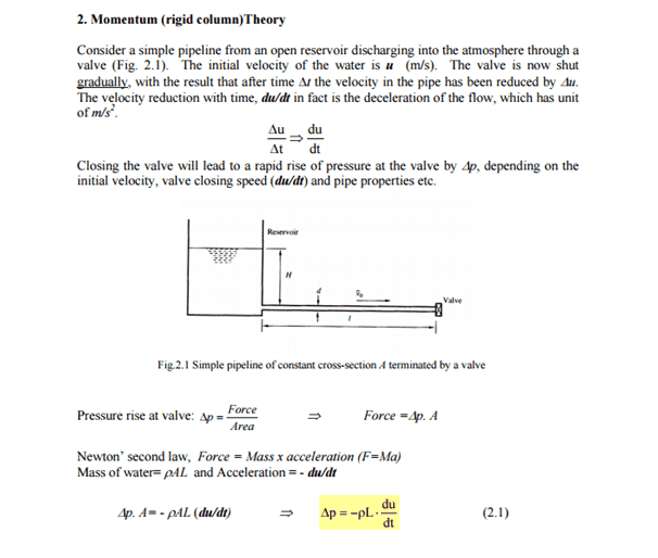
Diagram of a simple pipeline from a reservoir through a valve at the right end, with the pipe length labelled l, reservoir head H, and flow velocity u0 shown; text above reads Fig.2.1 Simple pipeline of constant cross-section A terminated by a valve.


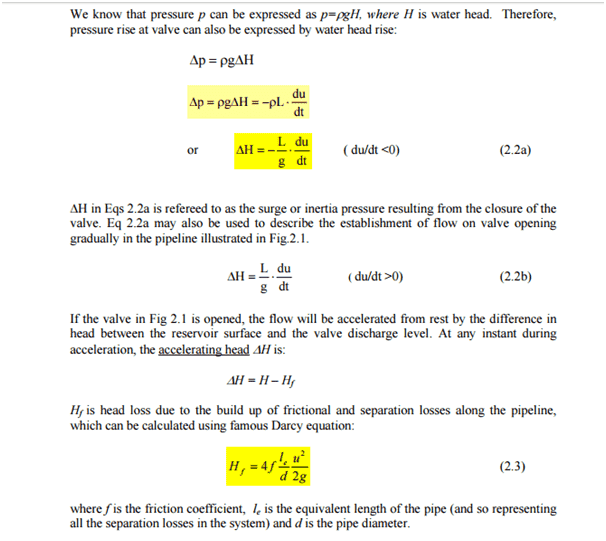
Typeset page of fluid mechanics equations: pressure as water head, surge head from valve closure (Eq 2.2a), head rise on opening (Eq 2.2b), accelerating head ΔH = H − Hf, and Darcy head loss Hf = 4f(le/d)(u²/2g) (Eq 2.3).


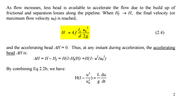
Printed text page with equations: H = 4f(Le u0^2)/(d 2g) labelled (2.4), accelerating head ΔH = H - Hf = H(1 - Hf/H) = H(1 - u^2/u0^2), and H(1 - u^2/u0^2) = (L/g)(du/dt).
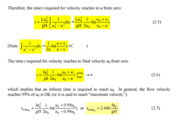
Typeset equations 2.5 to 2.7 in a fluid mechanics text deriving the time for velocity to reach u0 from zero, with an integral note and the 99% velocity time t = 2.646 Lu0/gH.
 
Last edited:
So the driving force / ##\left ( {\pi\over 4} d^2 \rho g \right ) \ \ ## ΔH is the head H at the entrance of the pipe minus the head loss in the pipe.
 
I've drawn so many diagrams and simply cannot show that delta H = H - Hf!
 
The explanations given in the attached document (the first post in this thread) are poor in my opinion.
Here is how I interpret it: when the valve closes, it seems to imply that a piezometer at the valve with show height H + ΔH
Hand-drawn sketch of a reservoir of height H connected by a horizontal pipe to a vertical piezometer tube, with a valve at the pipe base; the piezometer is labelled H and a small ΔH mark sits above the piezometer's fluid level.


Thus, if we define positive direction to the right,

∑forces on the fluid in horizontal pipe = m.a

(ρgH + ρ0).A - (ρg(H+ΔH) + ρ0).A = ρAL. dv/dt where: ρAL is the mass of fluid in the horizontal pipe and ρ0 is atmospheric pressure (A is pipe cross section)

This gives ΔH = - L/g dv/dt which implies that when delta H is positive, then there will be a deceleration of flow. Similarly, upon valve opening, we will see:
Hand-drawn sketch of a pipe system: a large tank on the left with water level H marked, a horizontal pipe running to a vertical standpipe on the right with height change ΔH marked, and flow arrows labelled SOME FLOW at the pipe outlet.

If positive direction still to the right,
∑forces on the fluid in horizontal pipe = m.a

(ρgH + ρ0)A - (ρg(H-ΔH) + ρ0)A = ρAL. dv/dt

thus ΔH = L/g dv/dt which implies that when delta H is as shown on the diagram, then there will be a deceleration of flow. Now, I always though that head loss was as shown in the following diagram:
upload_2017-1-5_13-54-5.png


I've drawn the energy grade line (EGL) and hydraulic grade line (HGL) as the piezometer. ΔH, as defined in diagram 2 on this post is shown in white. Delta H is not equal to H - Hf (Hf also called HL).

Hand-drawn sketch of a pipe reservoir with a vertical column labelled H on the left, a horizontal pipe, and a valve at the right end with labels H_L and V²/2g and the text SOME FLOW.


So, where have I gone wrong?
 
Attachments
  • Hand-drawn sketch of a reservoir on the left with depth H, a horizontal pipe leading right to a vertical standpipe with a level marked ΔH above a horizontal line, and a flow arrow labelled SOME FLOW at the outlet.
    upload_2017-1-5_13-46-27.png
    22.5 KB · Views: 721
To be honest, I so far only reacted to the part of your question I could recognize (##H_f##). For the pressure surge I have to read up too.
Text says they close the valve gradually, so the stuff keeps flowing. Instead of assuming a linear deceleration as in the link, the book stops with (2.2a), basically ## F = ma ##. So I agree with you, up to and including
axe34 said:
This gives ΔH = - L/g dv/dt which implies that when delta H is positive, then there will be a deceleration of flow.
Note that in fact so far we haven't said anything about the magnitude of ##\Delta H##.
Rememer that ##\Delta H## is a difference.

Upon valve opening, the inital head at he valve is H and the valve has to counter it with a force ##\rho g H A##. Any form of opening the valve lowers the force the valve can exercise on the liquid (the head at the valve), so there is a negative ##\Delta H## available to accelerate the cylinder of liquid.

So imho the baseline for ##\Delta H## in your second picture is the top line and ##\Delta H < 0##.

As such, I see no wrong in the treatment in the text: there are no excessive claims, just manipulation of a few equations.

Your third diagram depicts a steady state: ##{du\over dt}=0## so there is no ##\Delta H##.