Voltage regulator, tweaking capacitor values

Join the discussion
Ask a follow-up here, or get your own question answered by working scientists, mathematicians and engineers — people, not an autocomplete.
Real named experts · corrections over time · the nuance an AI answer skips
7 replies · 3K views
mishima
Messages
576
Reaction score
43
Hi, on page 23 of this datasheet (http://www.fairchildsemi.com/ds/LM/LM7805.pdf) the top figure 10 shows a setup for a fixed output regulator, for example suitable for logic chips which need a steady 5V. I was wondering how critical the values of capacitance were for C1 especially and also C0. I was also wondering how in theory these ideal values were calculated for this setup.

Here is another image from the book "Make: electronics" (taken from google) which shows the setup on top of a breadboard ready for logic chip experimentation. Not surprisingly the same capacitance values are suggested.
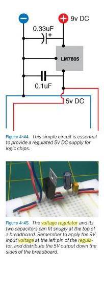
vretg.jpg


Based on the fine print on the datasheet I'm assuming the primary function of C1 is to filter noise from a nearby power supply. I don't own a .33 uF capacitor but could reach that value by combining other values, but I'm wondering if for example a .47 uF or .22 uF would perform just as well, rather than cluttering things up. Thanks.
 
Engineering news on Phys.org
For standard dropout regulators like the 7805, the capacitance values are not critical. The input capacitance is mostly for hold-up reasons (as any input power source falls off), and the output capacitance is to improve dynamic load regulation (decoupling).

For Low Dropout (LDO) voltage regulators, the capacitance values are much more important, because they are part of the stability design of the LDOs.
 
I think this is the reason for Note 2 on the datasheet. Correct me if I'm wrong Berkeman. Since the input voltage needs to remain 2 volts above the output voltage, CI would help maintain this for induced short negative spikes.
Notes:
1. To specify an output voltage, substitute voltage value for “XX.” A common ground is required between the input and the
output voltage. The input voltage must remain typically 2.0V above the output voltage even during the low point on the input
ripple voltage.
2. CI is required if regulator is located an appreciable distance from power supply filter.
3. CO improves stability and transient response.
 
Agreed. Standard voltage dropout regulators need to keep a pretty big input-to-output voltage margin.
 
The point that hasn't been made is that there should be ( by datasheet info) a 0.1 on the input AND output pins
These 2 caps are for the stability of the regulator and should be wired as close to the In, Out and GND pins as possible

so where the 0.1 uF position is shown on that breadboard construction is defeating the purpose of its inclusion

Any other electro's etc for smoothing are over and above the above requirementDave
 
So, why out of all the possible values did they choose to show a 0.33 uF capacitor?
 
interestingly the Fairchild 7805 does show the input cap at 0.33uF
the Texan Instruments one is 0.22uF
and as I commented earlier I have been more used to seeing data that used 0.1uF

mishima ... the value obviously doesn't need to be precise, but somewhere in the 0.1 to 0.47 would be acceptable.
Why something in that range of values ? ... probably after lots of testing/ circuit simulations, they found that its the best value for controlling oscillations.

cheers
Dave
 
Another thing is that the 7805 on page 3 has C1 as 0.1 uF, but the 7805A on page 12 has C1 as 0.33 uF. Anyways thanks, I need to remember theory is just one part of this stuff, and that testing/sims play a huge role.