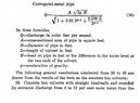
Water flow thru 18" corrugated culvert

Click For Summary
Calculating water flow through an 18-inch corrugated culvert requires understanding various parameters, including head, diameter, and cross-sectional area. The correct formula for discharge (Q) is influenced by factors such as headwater and tailwater levels, entrance conditions, and culvert slope. For accurate calculations, refer to the HDS5 document from the U.S. Department of Transportation, which outlines proper hydraulic design methods. It's important to note that some nomograms may provide inaccurate results for corrugated steel pipe culverts despite the equations being correct. For a practical flow rate measurement, one can assess the flow area and measure the time it takes for an object to pass through the culvert.
John1397
Messages
189
Reaction score
18
Attached formula can't figure out. H is 12 inches, Q is what I want to know, L is 40 feet, D is 18 inches, A I assume is area of 18 inches, g have no clue what this is. The Culver is 18" X 40 foot long coragated with water 1 foot over inlet and water on outlet 2" lower than culvert and the culverts tail is 2 inches lower than head. end
 

Attachments

  • Screenshot_20220730_103311~2.png
    Screenshot_20220730_103311~2.png
    27 KB · Views: 183
Engineering news on Phys.org
Q=discharge in cubic feet per second.
D=diameter of pipe in feet. 18" = 3/2 feet, radius = 3/4 ft.
A=cross-sectional area of pipe in square feet. = Pi * 9/16 sq ft.
L=length of culvert in feet. = 40 ft.
H=head on pipe in feet or the difference in the water level at the two ends. = (12+2+2)/12 ft.
g=acceleration of gravity. = 32 ? ft/s²

What is the problem?
 
If you are using this for an actual culvert, do not be surprised if the calculation seems to give a wrong answer. The correct procedure for calculating culvert flow is in a document titled HDS5 - Hydraulic Design of Highway Culverts, 3rd Edition. It's from the U.S. Department of Transportation, Federal Highway Administration. Here's a link: https://www.fhwa.dot.gov/engineering/hydraulics/pubs/12026/hif12026.pdf.

Be advised that at least one of the nomograms gives wrong answers for corrugated steel pipe culverts. The equations are correct. Note that one single equation cannot cover all cases of headwater level, tailwater level, entrance conditions, culvert slope, culvert length, approach velocity and direction, downstream channel velocity, inlet control vs outlet control, etc.

If you just want to know the flow rate of a nearby culvert, you could measure the flow cross sectional area and culvert length, then throw a stick in and measure the time to flow through. Velocity times area equals flow.
 
  • Informative
Likes berkeman and anorlunda
My idea is that I want to use immerse Whitetail Antlers in a fishtank to measure their volumetric displacement (the Boone and Crockett system is the current record measurement standard to place in a juxtaposition with) I would use some sight glass plumbed into the side of the tank to get the change in height so that I can multiply by the tank cross-section. Simple Idea. But... Is there a simple mechanical way to amplify the height in the sight glass to increase measurement precision...

Similar threads

  • · Replies 3 ·
Replies
3
Views
2K
  • · Replies 7 ·
Replies
7
Views
2K
Replies
1
Views
636
Replies
1
Views
3K
Replies
9
Views
2K
  • · Replies 6 ·
Replies
6
Views
14K
  • · Replies 6 ·
Replies
6
Views
9K
  • · Replies 1 ·
Replies
1
Views
4K
  • · Replies 3 ·
Replies
3
Views
3K
  • · Replies 3 ·
Replies
3
Views
2K