Discussion Overview
The discussion revolves around understanding the high and low turbine stages in a regenerative Rankine cycle, focusing on the specific states within the cycle and the associated efficiencies. Participants seek clarification on the definitions and implications of these stages, as well as visual representations of the cycle.
Discussion Character
- Exploratory
- Technical explanation
- Conceptual clarification
- Debate/contested
Main Points Raised
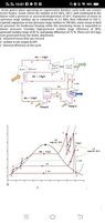
- One participant expresses confusion about the identification of high and low turbine stages, questioning whether the high turbine stage occurs at state 2 and the low turbine stage at states 3, 4, and 5.
- Several participants request clarification on the terminology used regarding states and seek visual aids, such as a T-s diagram, to better understand the cycle.
- A participant mentions the importance of efficiencies applied throughout the turbine, indicating that these efficiencies relate to specific segments of the cycle, such as 1-2' or 3-5'.
- Another participant points out the ideal case represented by vertical lines on the T-s diagram, where efficiency is considered to be 100%.
Areas of Agreement / Disagreement
The discussion reflects a lack of consensus on the definitions of high and low turbine stages, with multiple participants seeking clarification and expressing confusion. There are competing views on how to interpret the states and their associated efficiencies.
Contextual Notes
Participants have not yet resolved the definitions of the turbine stages, and there are references to external resources for clarification. The discussion includes requests for visual representations that may help in understanding the cycle better.
Who May Find This Useful
Individuals interested in thermodynamics, particularly those studying regenerative Rankine cycles or related engineering concepts, may find this discussion beneficial.