What Are the Functions and Circuit Analysis Techniques for Op-Amps?

  • Thread starter Thread starter InuyashaITB
  • Start date Start date
  • Tags Tags
    Op-amp
Join the discussion
Registration is free. Ask a follow-up in this thread, or start your own.
2 replies · 1K views
InuyashaITB
Messages
11
Reaction score
2
Hello again, Physics Forums.
I was studying this op-amp (no its not homework) and I am not sure if i am analyzing it correctly or not.
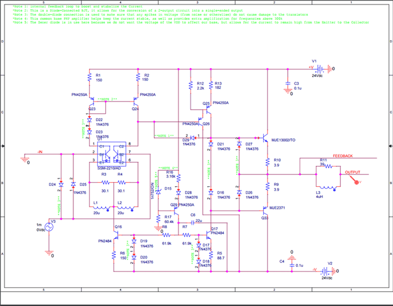
test-990_zpsw9suzksm.png


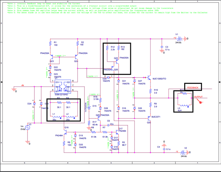
So far that is what I have. I was also wondering what the purpose of these highlighted sections are:
The RL circuits look like filters, but I don't quite understand why?
Also, i understand that the top one is a totem-pole, but I don't really understand what those are
test-990_zpsnyekgsqb.png
 
  • Like
Likes   Reactions: berkeman
Engineering news on Phys.org
The input stage has L in parallel with R. For fast signals the R will “degenerate” the differential pair gain, but the inductors will short circuit the resistors and so reduce the degeneration at low frequencies and DC. The roll-over frequency will be when the reactance of 20uH = 30.1 ohms. 30R1 / ( 2π * 20uH) = 240kHz.

The middle section is a voltage to current converter. The current balance between the collectors of Q24 and the +IN transistor, will integrate charge in the circuit capacitance to change the voltage input to Q26. R13 then produces a larger Q25 collector current proportional to the Q26 base voltage. The use of R12 makes Q24 and Q25 a fast darlington transistor.

The RL parallel circuit on the output isolates the output driver from the output load at high frequencies. That prevents output stage load dependent oscillation. Again, the output impedance is low for low frequencies and rolls over to approach 39 ohms above about f = 39R / ( 2π * 4uH) = 1.5MHz.
 
  • Like
Likes   Reactions: InuyashaITB
Wow, Thank you for giving such a detailed explanation Baluncore.
If I have any questions i'll make sure to ask here :)
 
  • Like
Likes   Reactions: dlgoff