pkc111
- 224
- 26
- TL;DR
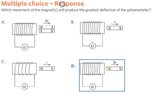
- What are the field strength and pattern rules for bar magnets attached to each other?
The attached probem tricked me because the answer is apparently D and not A.
Presumably because the magnetic field is weaker with 2 bar magnets joined N/S compared to a single bar magnet.
So this seems to be a gap in my knowledge as to the resulting strengths of magnets joined together. Are there any rules. I assume the magnetic strength is not 0 for the magnets in A, so what % loss will there be? What will the field lines look like? What if they were tied the other way N/N and S/S?
Many thanks