Why Are My Kirchhoff Voltage Rule Equations Incorrect?

  • Thread starter Thread starter bob1352
  • Start date Start date
  • Tags Tags
    Kirchhoff Voltage
Click For Summary
SUMMARY

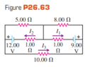
The discussion focuses on the application of Kirchhoff's Voltage Law (KVL) in circuit analysis, specifically addressing the incorrect equations derived for a circuit involving resistors of 1.00 Ω and 8.00 Ω. The user attempted to solve three loops but miscalculated the current values, resulting in I1 = 1, I2 = 2, and I3 = 0.2, which were incorrect. The key issue identified was the misunderstanding of current splitting at junctions, emphasizing the necessity of charge conservation, where the net current at any junction must equal zero.

PREREQUISITES
  • Understanding of Kirchhoff's Voltage Law (KVL)
  • Basic circuit analysis techniques
  • Knowledge of current splitting at junctions
  • Familiarity with Ohm's Law
NEXT STEPS
  • Review Kirchhoff's Current Law (KCL) for better understanding of current at junctions
  • Practice solving complex circuits using mesh analysis
  • Learn about the impact of resistor configurations on current distribution
  • Explore simulation tools like LTspice for circuit verification
USEFUL FOR

Electrical engineering students, circuit designers, and anyone involved in analyzing electrical circuits using Kirchhoff's laws.

bob1352
Messages
6
Reaction score
1
Homework Statement
Just for practice, not for any assignment
Relevant Equations
Kirchhoff Voltage Rule, Sum of Voltage Drops in Loop is Equal to Zero.
I tried doing three loops. For the bottom I did 9-I1(1) + I2(1) - I3(10) -12 = 0, for the upper left corner I did 12 - I2(1)- I2(5) = 0, for the upper right corner I did 9 - I1(1) - I1(8) = 0. I came to I1 =1, I2 =2 and I3 = .2. This was incorrect, I don't think I am summing the currents correctly. I have attached an image of the problem.
 

Attachments

  • Kirkoff Voltage Rule Problem.PNG
    Kirkoff Voltage Rule Problem.PNG
    5.4 KB · Views: 156
Physics news on Phys.org
Why do you have a term I1(8)? I1 is the current through the 1.00 Ω resistor. Is all that current also going through the 8.00 Ω resistor or does some of it split at the junction on the right? Same problem with the I2(5) term. To solve such circuits you need to make sure that charge is also conserved. This means that the net current through any junction must be zero.
 

Similar threads

Replies
4
Views
1K
  • · Replies 4 ·
Replies
4
Views
2K
Replies
22
Views
4K
  • · Replies 9 ·
Replies
9
Views
2K
Replies
10
Views
3K
Replies
10
Views
2K
  • · Replies 5 ·
Replies
5
Views
4K
Replies
16
Views
2K
  • · Replies 6 ·
Replies
6
Views
2K
  • · Replies 18 ·
Replies
18
Views
3K