Why can a fluid that satisfies the continuity equation cross streamlines?

  • Thread starter tracker890 Source h
  • Start date
  • Tags Tags
    Fluid dynamic
14 replies · 2K views · last reply
tracker890 Source h
Messages
90
Reaction score
11
Homework Statement
Confusing in the Conservation of Mass Flow Rate and mass cross streamlines
Relevant Equations
Continuity Equation
Control volume diagram with a streamline marked on the top boundary, labelled AD and BC mass flows, the velocity profile u = U sin(pi y / 2a) at the outlet, and U = 65 m/s at the inlet.

reference
reference_2
Q: Why can a fluid that satisfies the continuity equation for mass conservation cross streamlines?
 
Attachments
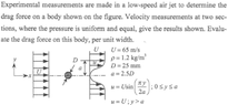
  • Diagram of a low-speed air jet flowing past a circular body of diameter D, with inlet velocity U on the left and a velocity profile u = U sin(pi y / 2a) for 0 <= y <= a and u = U for y > a at the downstream section, with a = 2.5D.
    1694564448072.png
    39.1 KB · Views: 151
  • Control volume diagram with a dash-dot centreline, labelled points A, B, C and D, and length a between A and the centreline. Inlet at left has uniform arrows labelled U = 65 m/s, outlet at right has a sine profile u = U sin(πy/2a), and mass flow arrows m_AD and m_BC cross the top and bottom boundaries.
    1694564587023.png
    29 KB · Views: 161
Last edited:
Mass can cross streamline, thats basically the definition of turbulent flow i.e. flow with heavy cross-stream mixing. It's not clear (to me) what you are taking issue with in this example?
 
erobz said:
Mass can cross streamline, thats basically the definition of turbulent flow i.e. flow with heavy cross-stream mixing. It's not clear (to me) what you are taking issue with in this example?
But this case is a steady flow, not a turbulent flow.
So I don't understand why fluid elements in steady flow can cross streamlines.
 
tracker890 Source h said:
But this case is a steady flow.
So your issue is with what is happening to the flow as it passes around the sphere. Where the streamlines are being squeezed together?
 
erobz said:
So your issue is with what is happening to the flow as it passes around the sphere. Where the streamlines are being squeezed together?
Why can ##\dot{m}_{AD}## and ##\dot{m}_{BC}## cross streamlines instead of being equal to zero?
 
I don't think fluid elements are crossing streamlines here. Streamlines are being divided, that not necessarily mass exchange between layers.

Imagine what is happening between streamlines. In steady flow a group of molecules are all together doing the same thing as the others in the streamline. The streamline is a boundary that is saying things inside it are doing the same thing on average. Then, they are presented with an obstruction, something that forces convective acceleration. That group of fluid particles is forced to divide into new groups, or layers such that the mass flowrate of that original grouping is conserved. In reality there is always some small turbulence from the change, but in theory the layer that "was one homogeneous unit" splits into new layers each having their own homogeneous velocity. Past the obstruction, they may settle back into the original formation.

Thats what I think is happening.
 
erobz said:
I don't think fluid elements are crossing streamlines here. Streamlines are being divided, that not necessarily mass exchange between layers.

Imagine what is happening between streamlines. In steady flow a group of molecules are all together doing the same thing as the others in the streamline. The streamline is a boundary that is saying things inside it are doing the same thing on average. Then, they are presented with an obstruction, something that forces convective acceleration. That group of fluid particles is forced to divide into new groups, or layers such that the mass flowrate of that original grouping is conserved. In reality there is always some small turbulence from the change, but in theory the layer that "was one homogeneous unit" splits into new layers each having their own homogeneous velocity. Past the obstruction, they may settle back into the original formation.

Thats what I think is happening.
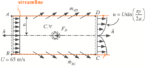
If fluid elements do not cross streamlines, then the diagram below would conflict with the principle of mass conservation. Is this an issue with the question or with my understanding?
Control volume diagram of a channel flow with corners A, B, C, D, a streamline marked at the top and bottom walls, inlet velocity profile U = 65 m/s, outlet profile u = U sin(pi y / 2a), and flow arrows crossing the top and bottom boundaries.
 
tracker890 Source h said:
If fluid elements do not cross streamlines, then the diagram below would conflict with the principle of mass conservation. Is this an issue with the question or with my understanding?
View attachment 331872
There are other streamlines in between the two drawn on the diagram.
 
erobz said:
There are other streamlines in between the two drawn on the diagram.
Is it related to ##\dot{m}_{AD}## and ##\dot{m}_{BC}## not being equal to zero?
 
tracker890 Source h said:
Is it related to ##\dot{m}_{AD}## and ##\dot{m}_{BC}## not being equal to zero?
I think the diagram is just saying the total mass flowrate splits around the sphere equally. I think they are just trying to illustrate it with the angled arrows. half goes up around, half goes down around.
 
erobz said:
I think the diagram is just saying the total mass flowrate splits around the sphere equally. I think they are just trying to illustrate it with the angled arrows. half goes up around, half goes down around.
I hope you can draw a simple diagram to assist in explaining, for better communication and understanding.
 
tracker890 Source h said:
I hope you can draw a simple diagram to assist in explaining, for better communication and understanding.
Diagram of a control volume ABCD around a streamline in a channel, with inflow U = 65 m/s on the left, a velocity profile u = U sin(pi y / 2a) at the outlet, mass flow arrows labelled m_AD and m_BD, outward normal n, and blue spheres with a drag force F_D.
 
  • Like
Likes   Reactions: tracker890 Source h
tracker890 Source h said:
Thank you
Your welcome!
tracker890 Source h said:
for the excellent and detailed explanation, along with my understanding diagram.
I'm not saying our diagrams are entirely accurate, but I think you have understood the idea.
 
  • Like
Likes   Reactions: tracker890 Source h
tracker890 Source h said:
Why can ##\dot{m}_{AD}## and ##\dot{m}_{BC}## cross streamlines instead of being equal to zero?
The obstruction in the flow forces some of the mass to spill out of the perfectly cylinder shape that has been represented.
While it recovers back to the initial state, the flow downstream the ball slowdowns.

That slowing moving mass becomes an additional physical obstacle, around which the surrounding fluid tries to move.
Pushing the layers away from the obstacle is the easiest way, but those (also moving) layers have inertia and resist that push (perpendicular to the flow).

Then, most of our molecules (that could not spill out into the outer layers), caught in between obstacle and outer layers, must increase velocity to keep mass flow balance (upstream-downstream).

In your diagram,

Flow mass AB cross section = Flow mass AD-BC cylinder wall + Flow mass CD cross section

Note the conical constant volume (cv) streamline shape represented in figure P3.44 in one of your reference links.

The closer to the obstruction the limits of the control volume are established, the more mass will cross it out in a transversal way (just to eventually cross back to the fill the void and return to be calmed still air).


  • Like
Likes   Reactions: erobz and tracker890 Source h