Can you please explain Bernoulli's equation?

In summary: Wouldn't the force increase as the front of the flow advances?F2 is the force due to the pressure difference between the two sides of the pipe.
  • #1
Callmelucky
144
30
Homework Statement
Theory not task
Relevant Equations
##p1+\frac{\rho(V1)^2} {2}=p2+\frac{\rho(V2)^2}{2}##
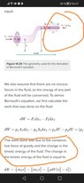
Can you please explain why is there work done by F2(on photo of textbook explanation of Bernoully equation (photo below)).

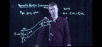
I can understand that W2 is caused by F2 which is gravitational force(screenshot photo from YT).

But for the explanation in textbook pipe is straight, no height difference, so what causes F2?

Is it the part of pipe that gets narrower(that "blocking affect", but shouldn't that be the cause for greater speed v2 compared to v1)?
Fluid in both cases(photos) is moving from left to right.

In textbook it's said that F2 is caused by surrounnding fluid, but how? If fluid is moving towards right side? And fluid is ideal(no resistance, not compressible).

Thank you.
 

Attachments

  • IMG_20230209_025440.jpg
    IMG_20230209_025440.jpg
    34.3 KB · Views: 81
  • Screenshot_20230209_025517_com.google.android.youtube.jpg
    Screenshot_20230209_025517_com.google.android.youtube.jpg
    23.3 KB · Views: 64
Last edited:
Physics news on Phys.org
  • #2
I believe Bernoulli assumes by edict that the fluid has a pressure at 1, and that the flow is only inviscid between 1 and 2. And note, just because there is no shear stress acting in the fluid through viscous action, there still are forces that arise from the momentum change the fluid element undergoes as it passes from 1 to 2. If the entire flow beyond 2 was inviscid and just a straight run of pipe I agree that ##F_2## could be in trouble… However, if section 1 to 2 were in closed loop there shouldn’t be an issue.
 
Last edited:
  • Like
Likes Callmelucky
  • #3
erobz said:
I believe Bernoulli assumes by edict that the fluid has a pressure at 1, and that the flow is only inviscid between 1 and 2. And note, just because there is no shear stress acting in the fluid through viscous action, there still are forces that arise from the momentum change the fluid element undergoes as it passes from 1 to 2. If the entire flow beyond 2 was inviscid and just a straight run of pipe I agree that ##F_2## could be in trouble… However, if section 1 to 2 were in closed loop there shouldn’t be an issue.
thanks, I thought I was missing something. Haven't learned yet anything about viscosity so I can't really understand what you are saying, but I am thankful that you have answered my question, now I know that there is nothing missing in materials I am learning from.
All the best 😊

Edit: I blame it on the authors, they could have written a note that says that ##F_2## is caused by viscosity, then I wouldn't bother people on the internet to explain me something I have paid them to do.
 
  • #4
Callmelucky said:
thanks, I thought I was missing something. Haven't learned yet anything about viscosity so I can't really understand what you are saying.
In a fluid with viscosity energy is converted to waste heat as it flows.

In the diagram below, the left side is what Bernoulli's says about flow through a straight section of pipe. If that section is the entire system according to Bernoulli's you can get any desired flowrate through that pipe at zero differential pressure. That is not consistent with reality, which is more like the right hand side-a statement of the first law that resembles Bernoulli's. If you desire more flow though that pipe in reality you must increase the differential pressure ( red bar labeled "s" for static head). That would then increase the energy lost (##T## for thermal energy) per unit length of the pipe.

1675915094894.png

Callmelucky said:
Edit: I blame it on the authors, they could have written a note that says that ##F_2## is caused by viscosity, then I wouldn't bother people on the internet to explain me something I have paid them to do.

You might be able to put the section in a closed loop and ignore viscosity altogether and still be consistent. It's tricker business describing all the nuance in fluid mechanics than you might initially expect. You kind of learn as you go.

Personally, I consider myself a "novice". So, if anything I'm saying isn't sitting well with you, please ask about it and if I can't explain it or if I'm incorrect someone here will.
 
Last edited:
  • #5
erobz said:
I believe Bernoulli assumes by edict that the fluid has a pressure at 1, and that the flow is only inviscid between 1 and 2. And note, just because there is no shear stress acting in the fluid through viscous action, there still are forces that arise from the momentum change the fluid element undergoes as it passes from 1 to 2. If the entire flow beyond 2 was inviscid and just a straight run of pipe I agree that ##F_2## could be in trouble… However, if section 1 to 2 were in closed loop there shouldn’t be an issue.
I doubt it has anything to do with viscosity. Wouldn’t the force increase as the front of the flow advances?
Maybe it's gas pressure ahead of the fluid?
@Callmelucky , doesn't the text define F2?
 
  • Like
Likes MatinSAR
  • #6
haruspex said:
I doubt it has anything to do with viscosity. Wouldn’t the force increase as the front of the flow advances?
Maybe it's gas pressure ahead of the fluid?
@Callmelucky , doesn't the text define F2?
You are probably correct, viscosity may not be a lynch pin here. If you put the section in a closed loop, I believe the issue can be avoided.
 
  • #7
erobz said:
In a fluid with viscosity energy is converted to waste heat as it flows.

In the diagram below, the left side is what Bernoulli's says about flow through a straight section of pipe. If that section is the entire system according to Bernoulli's you can get any desired flowrate through that pipe at zero differential pressure. That is not consistent with reality, which is more like the right hand side-a statement of the first law that resembles Bernoulli's. If you desire more flow though that pipe in reality you must increase the differential pressure ( red bar labeled "s" for static head). That would then increase the energy lost (##T## for thermal energy) per unit length of the pipe.

View attachment 321971You might be able to put the section in a closed loop and ignore viscosity altogether and still be consistent. It's tricker business describing all the nuance in fluid mechanics than you might initially expect. You kind of learn as you go.

Personally, I consider myself a "novice". So, if anything I'm saying isn't sitting well with you, please ask about it and if I can't explain it or if I'm incorrect someone here will.
honestly I am kinda short on time and I just study what I need to know to pass the test, so I don't go that much into depth. I posted this question because I didn't understand what caused ##F_2## and that bothered me.

What I am saying is that it would be nice if authors wrote something like ##F_2## is caused by viscosity or whatever else, just so that I can move on with studying, this way I kept thinking about ##F_2## and couldn't move on.
Or they could have just writte; ##F_2## exists, it's beyond of what you need to know right now, you will learn more about that in the future and I would be satisfied with that.

Thank you for trying to help me.
 
  • #8
haruspex said:
I doubt it has anything to do with viscosity. Wouldn’t the force increase as the front of the flow advances?
Maybe it's gas pressure ahead of the fluid?
@Callmelucky , doesn't the text define F2?
Nope, just that it's less in magnitude than ##F_1## and that it has opposite direction
 
  • #9
The surrounding fluid has a pressure, so it's going to apply a force to the fluid next to it.
 
Last edited:
  • Like
Likes Callmelucky
  • #10
vela said:
The surrounding fluid has a pressure, so it's going to apply a force to the water next to it.
What surrounding fluid? It's just water in pipe
 
  • #11
Callmelucky said:
What surrounding fluid? It's just water in pipe
Following @nasu's post, I notice that the pipe to the left of S1 appears empty. This suggests the fluid fills the pipe, left and right of the blue section. The colouring is just to highlight the fluid element being analysed.
 
  • #12
haruspex said:
Following @nasu's post, I notice that the pipe to the left of S1 appears empty. This suggests the fluid fills the pipe, left and right of the blue section. The colouring is just to highlight the fluid element being analysed.
So, you're saying that pipe is filled from both sides at the same time?
 
  • #13
vela said:
The surrounding fluid has a pressure, so it's going to apply a force to the fluid next to it.
unless you mean air? Because air is fluid
 
  • #14
Callmelucky said:
So, you're saying that pipe is filled from both sides at the same time?
No. There is fluid moving left to right along the whole pipe. The blue colour just picks out the body of fluid being analysed in the equation.
 
  • #15
haruspex said:
No. There is fluid moving left to right along the whole pipe. The blue colour just picks out the body of fluid being analysed in the equation.
I am not sure if we are on the same page but, fluid is allready moving in pipe and there is no friction. So force ##F_1## is causing acceleration, not steady continuous flow.
 
  • #16
Callmelucky said:
I am not sure if we are on the same page but, fluid is allready moving in pipe and there is no friction. So force ##F_1## is causing acceleration, not steady continuous flow.
Yes there is acceleration, even in steady state. Because the pipe gets narrower, the linear velocity has to increase. Some force has to supply the energy.
 
  • Like
Likes erobz
  • #17
Callmelucky said:
Or they could have just writte; ##F_2## exists, it's beyond of what you need to know right now, you will learn more about that in the future and I would be satisfied with that.

My bad. I thought you were having an existential crisis with Bernoulli. The simple answer is ##F_2## exists, and you will learn more about why that is later!

They are looking at it like a small section within the total flow. The forces are the from flow that is external to the element pushing on it. There is both flow behind the element pushing the element forward with ##F_1 = P_1A_1##, and flow in front of the element that is pushing opposite ##F_1## given as ##F_2 = P_2 A_2##. It is resisting the push from ##F_1##. That net force acting on the element is what accelerates the flow along a streamline ##s##.

In Bernoulli's, this acceleration is not a time varying acceleration, it is a position varying acceleration. Bernoulli's does not hold if the flow is characterized as "unsteady", (varying in time).
 
  • Like
Likes Callmelucky
  • #18
haruspex said:
Following @nasu's post, I notice that the pipe to the left of S1 appears empty. This suggests the fluid fills the pipe, left and right of the blue section. The colouring is just to highlight the fluid element being analysed.
Sorry, I did not post anything in this thread. I mean, until now. You mean someone else, I suppose.
 
  • #19
Here is an exploration to get an understanding of Bernoulli's limitations if you want to try.

What would Bernoulli's tell you the rate of work supplied by the pump in each of these two scenarios is when going clockwise with the flow around the loop from ##1 \to 2##?

1675966711527.png
 
Last edited:
  • Like
Likes Lnewqban
  • #20
erobz said:
Here is an exploration to get an understanding of Bernoulli's limitations if you want to try.

What would Bernoulli's tell you the rate of work supplied by the pump in each of these two scenarios is when going clockwise with the flow around the loop from ##1 \to 2##?

View attachment 321996
I am not sure I understand 100% of what you are saying or rather I am not sure I understand the problem, but if I need to just tell which scenario would need less energy(work) to circulate the water from point 1 to point 2 I'd say it's left scheme, because there is no that ##F_2## that we talked about, but yet again there is no increase in speed so the pump would have to pump longer time to complete the cycle, so I am not sure really.
 
  • #21
Why the problem uses S and s for different things?
Also the transition of cross-sections should be smooth rather than abrupt.

@Callmelucky , are you familiar with roller coaster problems?
This is very similar.

Bernoulli’s equation is about conservation of energy within a fluid.
That energy can be observed in three forms, according to what we can measure: static pressure, height pressure or potential energy, and velocity or dynamic pressure.

Imagine we have a L-shaped pipe of uniform and small cross-section, with a valve at the vertical-horizontal transition or bend.
The vertical leg is full of water and the horizontal one is empty.
Both ends are open to the atmosphere.

What the equation of balance of energy discovered by Bernoulli tells us about our L-shape set up?
We only have potential energy, as the water is not flowing.

Then, we quickly open the valve and the column of water begins to free-fall, while water flows horizontally.
That seems to be the instant represented in the picture of your book.
The internal energy of the fluid remains the same, gradually changing from potential to dynamic.

Once the column is depleted, the water flows at constant velocity for ever inside the horizontal leg of our pipe.
That velocity is limited by the amount of potential energy that the column initially had.

If the cross-section of the horizontal leg eventually changes, the velocity must adjust to it.
As height or potential energy remains the same, the only available term of the equation for velocity to exchange energy with is static pressure.

Please, see:
https://courses.lumenlearning.com/suny-osuniversityphysics/chapter/14-6-bernoullis-equation/
 
  • Like
Likes Callmelucky
  • #22
Callmelucky said:
I am not sure I understand 100% of what you are saying or rather I am not sure I understand the problem, but if I need to just tell which scenario would need less energy(work) to circulate the water from point 1 to point 2 I'd say it's left scheme, because there is no that ##F_2## that we talked about, but yet again there is no increase in speed so the pump would have to pump longer time to complete the cycle, so I am not sure really.
Just apply Bernoulli's at 1 to 2 for each system. What do you get for the pressure differential across the pumps in each case. i.e. what is ##\Delta P = P_1 - P_2## in each system?

Then in general, the rate of work for the pump is given by:

$$\dot W_p = \Delta P \cdot Q$$

##Q## is the volumetric flowrate
 
  • #23
nasu said:
Sorry, I did not post anything in this thread. I mean, until now. You mean someone else, I suppose.
Sorry, I meant @vela.
 
  • #24
Callmelucky said:
I am not sure I understand 100% of what you are saying or rather I am not sure I understand the problem, but if I need to just tell which scenario would need less energy(work) to circulate the water from point 1 to point 2 I'd say it's left scheme, because there is no that ##F_2## that we talked about, but yet again there is no increase in speed so the pump would have to pump longer time to complete the cycle, so I am not sure really.
Your intuition was headed in the correct direction for the power to circulate a real flow.

If this were a real system, we would expect the system on the right to require more power to circulate at any given volumetric flow rate, for one reason; Higher viscous losses per unit length - from higher velocity in the contraction.

However, I was hoping you would blindly apply Bernoulli's for this system and see what pops out of the theory for such a system.

The theory will deduce that neither of them will require any power to circulate any desired flow. The pumps will push whatever flow around the loop at no differential pressure and no expenditure of energy.
 
  • #25
Lnewqban said:
Why the problem uses S and s for different things?
S is for area and s is for distance
Lnewqban said:
are you familiar with roller coaster problems?
This is very similar.
I am not.
Lnewqban said:
Bernoulli’s equation is about conservation of energy within a fluid.
That energy can be observed in three forms, according to what we can measure: static pressure, height pressure or potential energy, and velocity or dynamic pressure.
I believe I understand the differences, Hydrostatic pressure is due to depth on static fluid, static pressure in closed pipe with constant velocity is calculated by drilling a hole in the pipe and meassuring how high fluid rises in that pipe * ##\rho## * g + ##\rho## * g * distance of point in the fluid from top of the pipe, and dynamic pressure is same that but L shaped pipe is placed in tube and it's fixed so that pressure is higher than static, those two combined give total pressure.

So could it be that static pressure drops because the tube becomes narrower(static pressure drops with decrease of diameter of tube)?

And one more thing(I guess I really did have an existential crisis with ##F_2## after all @erobz)

Could this ##F_2##(pic in attachments) acting in opposite direction(thus doing negative work) be representation of loss loss of energy due to inelastic collision(kinetic energy is not the same before and after collision) between water molecules and tube wall(the one that gets narrower)? And gravitational force, ofc.
 

Attachments

  • Screenshot_20230210_044737_com.android.chrome_edit_1224921782333402.jpg
    Screenshot_20230210_044737_com.android.chrome_edit_1224921782333402.jpg
    25 KB · Views: 69
  • #26
Callmelucky said:
Could this ##F_2##(pic in attachments) acting in opposite direction(thus doing negative work) be representation of loss loss of energy due to inelastic collision(kinetic energy is not the same before and after collision) between water molecules and tube wall(the one that gets narrower)? And gravitational force, ofc.
No it couldn't, they are assuming no loss of energy as heat in between 1 and 2.
 
  • #27
erobz said:
Just apply Bernoulli's at 1 to 2 for each system. What do you get for the pressure differential across the pumps in each case. i.e. what is ##\Delta P = P_1 - P_2## in each system?

Then in general, the rate of work for the pump is given by:

$$\dot W_p = \Delta P \cdot Q$$

##Q## is the volumetric flowrate
for 1st scenario ##\Delta P=P_1 - P_2 = 0##.
But, for 2nd scenario I'd say that first pressure drops then increasesy but that is not what I have seen in experiment from YT, guy did experiment with venturi tube(pics in attachment) and I expected for 1 and 3rd pillar to be the same height, but they weren't.
 

Attachments

  • Screenshot_20230210_141412_com.google.android.youtube.jpg
    Screenshot_20230210_141412_com.google.android.youtube.jpg
    23.5 KB · Views: 53
  • Screenshot_20230210_141423_com.google.android.youtube.jpg
    Screenshot_20230210_141423_com.google.android.youtube.jpg
    22.2 KB · Views: 49
  • #28
Callmelucky said:
for 1st scenario ##\Delta P=P_1 - P_2 = 0##.
But, for 2nd scenario I'd say that first pressure drops then increasesy but that is not what I have seen in experiment from YT, guy did experiment with venturi tube(pics in attachment) and I expected for 1 and 3rd pillar to be the same height, but they weren't.
In Bernoulli's they are the same height. It is an idealization of reality where there is no thermal energy lost between the two points in question. The experiment is conducted in reality, not in the idealization. So given that, what does Bernoulli say about the differential pressure across the pump in the second system?
 
  • Like
Likes Callmelucky
  • #29
erobz said:
In Bernoulli's they are the same height. It is an idealization of reality where there is no thermal energy lost between the two points in question. The experiment is conducted in reality, not in the idealization. So given that, what does Bernoulli say about the differential pressure across the pump in the second system?
Yeah but it can't be that big difference.
I mean, I can say what you have written and I believe it's true(that there is no difference), it's just that I don't understand why is then such a big difference between 1st and 3rd pillar or colored water.
 
  • #30
Callmelucky said:
Yeah but it can't be that big difference.
I mean, I can say what you have written and I believe it's true(that there is no difference), it's just that I don't understand why is then such a big difference between 1st and 3rd pillar or colored water.
Thats because of viscosity and air is also compressible. It adds a whole other layer of complexity to predicting the outcome of that experiment. Also "such a big difference" is a relative term here. The actual difference in pressure is , in terms of absolutes, small ( maybe 2"W.C. ?) , but clearly measurable. Furthermore, we have no idea what the velocity of the flow is in that experiment. Viscous losses go as ##\propto V^2##.

Bernoulli's pretends none of that exists.
 
Last edited:
  • Like
Likes Callmelucky
  • #31
erobz said:
Thats because of viscosity and air is also compressible. It adds a whole other layer of complexity to predicting the outcome of that experiment. Also "such a big difference" is a relative term here. The actual difference in pressure is , in terms of absolutes, small ( maybe 2"W.C. ?) , but clearly measurable. Furthermore, we have no idea what the velocity of the flow is in that experiment. Viscous losses go as ##\propto V^2##.

Bernoulli's pretends none of that exists.
But I still don't understand what causes that ##\F_2## because it's not viscosity and if the pipe is at the same height all the time than there is no gravitational force either.
 

Attachments

  • Screenshot_20230210_151308_com.android.chrome_edit_1255697608056310.jpg
    Screenshot_20230210_151308_com.android.chrome_edit_1255697608056310.jpg
    22.5 KB · Views: 52
  • #32
If Euler's differential force balance equation for an inviscid fluid is dotted with the fluid velocity vector, Bernoulli's equation automatically emerges. This is the mechanical energy balance equation for an inviscid fluid.
 
  • Like
Likes Callmelucky
  • #33
Chestermiller said:
If Euler's differential force balance equation for an inviscid fluid is dotted with the fluid velocity vector, Bernoulli's equation automatically emerges. This is the mechanical energy balance equation for an inviscid fluid.
So, the Euler differential force causes ##F_2##?

edit: I mean, the bernoully equation is consequence of Euler diff. force balance eq...?
 
  • #34
I mean, then I probably won't have to calculate the ##F_2## in high school , right?
 
  • #35
Callmelucky said:
But I still don't understand what causes that ##\F_2## because it's not viscosity and if the pipe is at the same height all the time than there is no gravitational force either.
The fluid element is being compressed by its container and the fluid surrounding the element. It's under pressure. Thus, when we isolate the element from its surroundings to analyze it, we need to replace the effect of the surroundings as external forces acting on the element. The net effect of all those forces (and others not shown-like weight) dictates whether or not the element is accelerating in a particular direction.

1676040668812.png


When you first started this, I was thinking you were seeing some seeming contradictions that can arise in certain systems where Bernoulli's gives spectacularly unrealistic results because of the inviscid assumption applied to an entire system. But, it just dawned on me (when you kept asking about ##F_2## and mentioned about calculating it in high school) that you probably just don't understand how we apply Newtons Second Law to analyze fluid systems. The average Mech. Engineers don't get into fluid mechanics until sophomore\junior year in college (I think). Sorry, If I caused any confusion in that regard. So lets back up, and I think we can get this resolved.
 
Last edited:
  • Like
Likes Callmelucky
<h2>1. What is Bernoulli's equation?</h2><p>Bernoulli's equation is a fundamental principle in fluid dynamics that describes the relationship between the velocity, pressure, and elevation of a fluid moving along a streamline. It states that as the speed of a fluid increases, the pressure decreases, and vice versa.</p><h2>2. How is Bernoulli's equation derived?</h2><p>Bernoulli's equation is derived from the principle of conservation of energy, which states that the total energy of a system remains constant. By applying this principle to a fluid moving along a streamline, we can derive Bernoulli's equation.</p><h2>3. What are the assumptions of Bernoulli's equation?</h2><p>The assumptions of Bernoulli's equation are that the fluid is incompressible, inviscid (has no viscosity), and flows along a streamline. It also assumes that there is no energy loss due to friction or turbulence.</p><h2>4. How is Bernoulli's equation used in real-world applications?</h2><p>Bernoulli's equation is used in many real-world applications, such as in the design of airplane wings, water pumps, and carburetors. It is also used in weather forecasting, aerodynamics, and hydraulics.</p><h2>5. Can Bernoulli's equation be applied to all types of fluids?</h2><p>No, Bernoulli's equation can only be applied to incompressible fluids, such as water or air at low speeds. It cannot be applied to compressible fluids, such as gases, or to fluids at high speeds where there is significant turbulence and energy loss.</p>

1. What is Bernoulli's equation?

Bernoulli's equation is a fundamental principle in fluid dynamics that describes the relationship between the velocity, pressure, and elevation of a fluid moving along a streamline. It states that as the speed of a fluid increases, the pressure decreases, and vice versa.

2. How is Bernoulli's equation derived?

Bernoulli's equation is derived from the principle of conservation of energy, which states that the total energy of a system remains constant. By applying this principle to a fluid moving along a streamline, we can derive Bernoulli's equation.

3. What are the assumptions of Bernoulli's equation?

The assumptions of Bernoulli's equation are that the fluid is incompressible, inviscid (has no viscosity), and flows along a streamline. It also assumes that there is no energy loss due to friction or turbulence.

4. How is Bernoulli's equation used in real-world applications?

Bernoulli's equation is used in many real-world applications, such as in the design of airplane wings, water pumps, and carburetors. It is also used in weather forecasting, aerodynamics, and hydraulics.

5. Can Bernoulli's equation be applied to all types of fluids?

No, Bernoulli's equation can only be applied to incompressible fluids, such as water or air at low speeds. It cannot be applied to compressible fluids, such as gases, or to fluids at high speeds where there is significant turbulence and energy loss.

Similar threads

Replies
1
Views
957
  • Introductory Physics Homework Help
Replies
14
Views
2K
  • Introductory Physics Homework Help
Replies
7
Views
5K
  • Mechanics
Replies
2
Views
2K
  • Mechanical Engineering
Replies
31
Views
2K
  • Introductory Physics Homework Help
Replies
3
Views
3K
  • Classical Physics
2
Replies
35
Views
2K
  • Introductory Physics Homework Help
Replies
2
Views
2K
  • Classical Physics
2
Replies
48
Views
2K
Replies
4
Views
1K
Back
Top