paulmdrdo
- 89
- 2
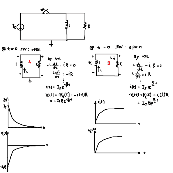
as you can see In the image I provided I have derived the equation for i(t) and v(t).
On circuit A I use a passive sign convention(current flowing from positive to negative) on the inductor, hence the equation and their corresponding graph.
i(t) is decaying exponentially, v(t) is decaying exponentially.
On circuit B I did use what I learned in physics, i.e the voltage induced across an inductor is always opposite to the increase/decrease in current
flowing throuhg it. Since the current i(t) is decreasing, the voltage should support that current hence the sign. when I perform kvl on circuit B I ended up having growth equation for both i(t) and v(t). Why is that?
Also in circuit A I expect to have same graph for both i(t) and v(t) (Although they are both decaying).
Please, kindly clear this up for me if you have time. Thanks!
On circuit A I use a passive sign convention(current flowing from positive to negative) on the inductor, hence the equation and their corresponding graph.
i(t) is decaying exponentially, v(t) is decaying exponentially.
On circuit B I did use what I learned in physics, i.e the voltage induced across an inductor is always opposite to the increase/decrease in current
flowing throuhg it. Since the current i(t) is decreasing, the voltage should support that current hence the sign. when I perform kvl on circuit B I ended up having growth equation for both i(t) and v(t). Why is that?
Also in circuit A I expect to have same graph for both i(t) and v(t) (Although they are both decaying).
Please, kindly clear this up for me if you have time. Thanks!
Last edited by a moderator: