Why is my Transistor Reducing Voltage in Buck Converter Modeling?

3 replies · 2K views · last reply
Chacabucogod
Messages
56
Reaction score
0
Hi I'm currently modeling a 5-12Vdc buck converter, and just out of nowhere decided to put a transistor between the output resistance and the diode. Now, this transistor is always connected to voltage so it shouldn't do anything at all, it's just a closed switch. What happens is that the transistor ends up eating a lot of the voltage. I don't really understand what's happening.
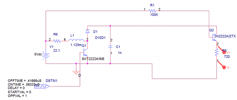
Circuit schematic of a buck converter simulation with a 5Vdc source, R6 22.1, inductor L1 1.120m, transistor Q1 SXT2222A/SIE, diode D10D1, capacitor C1 1n, load resistor R5 720 and R1 100K, driven by a DSTM1 pulse source.
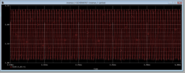
Simulator screenshot of a time-domain plot of V(R5:2,R5:1) from 3.90 ms to 4.00 ms, showing a rapidly switching red waveform oscillating between about 2.1 V and 3.4 V on a 2.00 to 3.50 V axis.

Resistance Voltage. It's 2... when it should be 12.
 
What is the V at the Emitter of Q2 Relative to the base of Q2?
 
Looks like that a demand for a transistor DC gain (Icollector/Ibase) must be pretty high in this example.
Check out 2N2222A transistor's characteristics curves.