Amplify ferrite core solenoid electromagnetic range

In summary, you are trying to create a DIY RF link and you need to increase the range of the receiver. The receiver you are using right now is probably not able to handle the max range you are looking for. You should probably look into using an off-the-shelf transmitter/receiver pair or using optical communication.
  • #1
mehadao
4
0
Hello all,

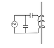
I'm playing around with a PIC + LCC Tank to send - at a 5MHz frecuency - some numeric data via BPSK. The receiver is a loop antenna placed in the ground.

The sender antena (L) is a ferrite core solenoid (N=10). As having a larger core, or increasing the Number of coils around the ferrite is having no much larger effect on the max. range which I can place the sender from the loop antenna (ground receiver)- what kind of amplificator can I use to increase the current in the coil an obtain a larger range?

The PIC I am using to send the instructions through the coil is a PIC16F.

Any worth reading reference that may cover this purpose?

Thanks in advance for your time.
 

Attachments

  • LCC.PNG
    LCC.PNG
    2 KB · Views: 96
Engineering news on Phys.org
  • #2
Welcome to PF. :smile:

You have to be careful trying to create DIY RF links if you don't have a lot of experience with them. It's pretty easy to create harmful Electromagnetic Interference (EMI), which can get you in trouble with the FCC or whatever government agency manages the RF spectrum in your country.

What is the project? What RF experience do you have? What exactly do you need this link to do?

A better option would probably be to use some off-the-shelf licensed transmitter/receiver pair to do this, or use optical communication to provide you the 1-way data link. If you tell us more about your goals in this project, hopefully we can help you do this without generating any EMI.
 
  • #3
BTW, if your transmitter is low enough power, you may be able to still transmit and not get in trouble for EMI. But without a fair amount of test equipment, it's hard to know if your power is below the legal limit, and whether any sidebands or harmonics are an issue as well.
 
  • #4
Thanks for your help @berkeman :biggrin:

The project is a transponder - where the transponder (the coil element) send it's ID number, and the ground loop detects when has crossed the antenna.

Right now the max height that the transponder can be detected is around 60cm - but I'm a bit stuck with increasing that up to 1 meter.

This is just DIY project but of course trying to complain with CE regualtions.

Any ideas? Thanks!
 
  • #6
Thanks for your help @anorlunda

It is quite similar to active-rfid/beacon (according to the blog description)

Until now, the info transmission and a basic design is working. I was just looking for a way to increase the range of the beacon/receiver max. separation.

As the PIC is the one sending the info via BPSK, I don't know if setting up some MOSFET between the PIC pins and the coil will affect in some way.
 
  • #7
In that case, you should be able to get along with very lower power and thus avoid violating FCC regulations. If you DIY, it's your responsibility to learn what the regulations require. Here's some technical data from an active RFID I found on Ebay.

  • Rated voltage: DC12V
  • Operating frequency: 2.4-2.48G
  • The maximum current: 100mA
  • Power: -25~0dBm
  • Reading distance: max80m
  • Antenna polarization:Circular polarization
  • Rate of communication: 1000Kbit/s
  • Attenuation regulation: 2-80 meter can be adjusted
  • Communication interface: WIEGAND26
  • Power angle: level: 55 degrees, vertical:25 degrees
  • Size: 318x200x100cm
  • Package size:45x32x14cm
  • Shell: ABS waterproof shell, cast aluminum bottom box
 
  • #8
mehadao said:
I was just looking for a way to increase the range of the beacon/receiver max. separation.
You do not need more transmit power. You need to improve the receiver gain.
What do you use now as the receiver ?

You must also study how the relative orientation of the antenna loops change with travel.
 
  • Like
Likes berkeman
  • #9
Baluncore said:
What do you use now as the receiver ?
Right now, I am using a differential amplifier with current mirror.

Where Q1 and Q2 are 2N3904, and Q3 and Q4 are 2N3906.

In parallel with the input lines, I have a capacitor to tune the frecuency to 5MHz according to the antenna loop size (uH), and the loop too.

I have no found any content - which I am able to understand and adapt to my project - around the internet.

Any ideas will be much appreacited :smile:

Thanks for your support!
 
  • #10
mehadao said:
Any ideas will be much appreacited
We don't really know how you are doing it, so it is a bit hard to guess where we can best help.

I doubt a PIC could generate more than 50 mW of RF from an IO pin, so I think it is worth looking at your experimental setup and seeing what can be done to increase the range, and maybe reduce the power needed by the PIC.

The more answers you give us, the more we can help.
What is the 5 MHz ? Is it a carrier frequency or is it the data rate ? We need to know both.

Are you directly driving a tuned LC transmit coil with a phase modulated square wave from a logic pin on a PIC16Fxx? If so, I would want to make sure the transmit antenna was wide band, and that the receive antenna was also sufficiently wide. For BPSK you will need to have a bandwidth of twice the data rate, centred on the carrier.

Have you simulated the circuits you have built with some version of Spice ?
Please post your transmit circuit, from the PIC to the TX loop. Also post the full circuit for the RX differential amplifier, including the bias circuit. You can attach the picture to a post.

The antennas will be important.
What is the diameter of the ground based RX coil? Does it have a vertical axis ?
What is the diameter of the vehicle based TX coil? Does it have a vertical axis ?

Does the vehicle travel outside the RX coil area, where the polarity of the carrier might fall to zero and then invert.
 

1. What is a ferrite core?

A ferrite core is a type of magnetic material that is commonly used in electronic devices to increase the strength of an electromagnetic field. It is made of a ceramic compound of iron oxide and other metal oxides.

2. What is a solenoid?

A solenoid is a coil of wire that is used to create a magnetic field when an electric current is passed through it. It is often used in electronic devices to convert electrical energy into mechanical motion.

3. How does a ferrite core amplify the electromagnetic range of a solenoid?

A ferrite core is placed inside the solenoid and acts as a magnetic amplifier. It concentrates and directs the magnetic field created by the solenoid, making it stronger and increasing its range and effectiveness.

4. What are the benefits of using a ferrite core in a solenoid?

The use of a ferrite core in a solenoid can improve its efficiency and performance. It can also reduce energy loss and help to minimize interference from other electromagnetic fields.

5. Are there any limitations to using a ferrite core in a solenoid?

Yes, there are some limitations to using a ferrite core in a solenoid. The size, shape, and material of the core must be carefully chosen to match the specific application. Additionally, the core can only amplify the magnetic field up to a certain point before it becomes saturated and can no longer increase the range.

Similar threads

  • Electrical Engineering
2
Replies
61
Views
8K
Replies
4
Views
2K
Back
Top