- #1
The Tortoise-Man
- 95
- 5
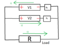
I would like to do now (theoretically) a couple of rather naive things with two batteries with voltages ##V_1## and ##V_2## in parallel charged with an abstract load with resistance ##R##.
Usually, one learns in elementary electronics that the only "right" configuration with batteries in parallel is given by (M1), at least in case ##V_1=V_2##:

Now the story becomes weird. What is the precise physical explanation why following configuration causes damage where we swap the poles, or asking differently how to model the system's behavior in following case - call it (M2):

The "layman argument" which I often read but which not persuades me is that it causes short circuit in this area:

Well, but applying the same "logic" one could also say that there is also a short circuit
in (M1), or not?
 Why this "short circuit argument" is valid for (M2), but not for (M1).
Therefore up to now I'm not happy with this way of reasoning, but maybe I'm missing the whole point. Can this argumentation refute my objection that seemingly the same reasoning may be naively thinking applied to (M1), too? What is the precise difference in the two cases? In other words, why connecting poles in "right" way - as in (M1) - not causes a short circuit - but (M2) does?
If this "Dr Google argumentation" is indeed too sloppy, is there a reasonable advanced argumentation explaining why configuration in (M2) damages the system? Is there a reasonable mathematical model predicting such behavior? Possibly, is it sufficient to reasoning with Kirchhoff's junction and voltage rules in naive way or does one need more advanced techniques from electrochemistry to answer the problem qualitatively satisfactory?
What about the story with ##V_1 \neq V_2##? Which behaviour of the system is going to be predicted for configs (M1) and (M2)?
Usually, one learns in elementary electronics that the only "right" configuration with batteries in parallel is given by (M1), at least in case ##V_1=V_2##:
Now the story becomes weird. What is the precise physical explanation why following configuration causes damage where we swap the poles, or asking differently how to model the system's behavior in following case - call it (M2):
The "layman argument" which I often read but which not persuades me is that it causes short circuit in this area:
Well, but applying the same "logic" one could also say that there is also a short circuit
in (M1), or not?
Therefore up to now I'm not happy with this way of reasoning, but maybe I'm missing the whole point. Can this argumentation refute my objection that seemingly the same reasoning may be naively thinking applied to (M1), too? What is the precise difference in the two cases? In other words, why connecting poles in "right" way - as in (M1) - not causes a short circuit - but (M2) does?
If this "Dr Google argumentation" is indeed too sloppy, is there a reasonable advanced argumentation explaining why configuration in (M2) damages the system? Is there a reasonable mathematical model predicting such behavior? Possibly, is it sufficient to reasoning with Kirchhoff's junction and voltage rules in naive way or does one need more advanced techniques from electrochemistry to answer the problem qualitatively satisfactory?
What about the story with ##V_1 \neq V_2##? Which behaviour of the system is going to be predicted for configs (M1) and (M2)?
Last edited: