Approach analytical calculation for a beam frame

In summary, Roark will have the equations for a beam with simple supports, center load, and a moment at each end of the beam. It will also have the equation for a column with one end fixed and a moment load on the other end. The assumption of the column bases fixed is a reasonable assumption IFF the baseplates are thick enough, and bolted tightly enough to a thick enough concrete base. Otherwise, you need either an assumption of base bending stiffness or simply supported bases on the columns. It's a lot of algebra, but very doable.
  • #1
Mech_LS24
148
16
TL;DR Summary
I would like to know if my analytical approach for the deflection of an frame is correct.
Hi all,

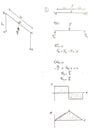
Currently I am working on a home-project, making a trike. Now just for fun and because I like to calculate things, I calculated the deflection of a frame with a load. The frame is shown in the picture below, I added the force for clarity.

With my analytical calculation I found a deflection of 0.016 mm, with a load of 800 Newtons. Are the following assumptions correct?:
  • Point B and C are fixed, this means L1 doesn't play a role in this calculation.
  • Reaction forces at point B and C are 0.5*F.

I did a cross check in Simulation and found a deflection of 0.039 mm, how can I get a 'more' accurated analytical calculation? The difference of those two (>50%) is quite a lot, isn't it?
Analytical_calc_01.jpg


Analytical_Calc.PNG
 
Engineering news on Phys.org
  • #2
Your first assumption is not correct, your second assumption is correct if the load is centered. The sketch below shows the deflection under the assumption that the bases of the columns are fixed.
Frame.jpg

There may be an equation in Roark for this case: https://www.amazon.com/dp/007072542X/?tag=pfamazon01-20.

If not, Roark will have the equations for a beam with simple supports, center load, and a moment at each end of the beam. It will also have the equation for a column with one end fixed and a moment load on the other end. Solving this case is "merely" a matter of setting the angular deflection of the ends of the beam equal to the angular deflection of the end of the column. You can simplify by cutting the model in half at the center, and adding a moment to the free end of the beam so as to make beam end slope zero.

The assumption of the column bases fixed is a reasonable assumption IFF the baseplates are thick enough, and bolted tightly enough to a thick enough concrete base. Otherwise, you need either an assumption of base bending stiffness or simply supported bases on the columns.

It's a lot of algebra, but very doable. It will keep you entertained for a few hours.
 
  • Informative
  • Like
Likes berkeman and Mech_LS24
  • #3
jrmichler said:
It will also have the equation for a column with one end fixed and a moment load on the other end
You mean this one below?
1633410761376.png


jrmichler said:
You can simplify by cutting the model in half at the center, and adding a moment to the free end of the beam so as to make beam end slope zero.
The sketch below is what you are saying right? I am trying learning myself as well a decent approach solving 'exercises' like this. Please don't hesitate giving advise in detail :).
FBD_half_frame_analy.jpg
 
  • #4
You have to break the half frame down to two parts, a beam and a column, as shown below.
FBD Frame.jpg

The column has a vertical force which can be ignored. The column has one end fixed and a moment on the other end. That moment causes the end of the column to deflect to an angle ##\theta##.

The beam has vertical forces and moments at each end. The moment at the right end is calculated to force the beam deflection angle to be zero at that end. The moment at the left end is calculated to force the beam deflection angle ##\theta## to be equal to the column deflection angle ##\theta##.

You end up with a series of simultaneous equations to be solved. If it looks challenging, it's because the problem is straight from a graduate level strength of materials course that I took in 1978. And never used since.

In the real engineering world, a problem like this is normally solved by assuming that the beam is simply supported. The resulting calculation will be somewhat conservative. If it is a weight critical aerospace situation, it would be solved using FEA. But, it is a great training exercise to learn more about interactions in complex structures.
 
  • Like
Likes Mech_LS24
  • #5
jrmichler said:
The column has one end fixed and a moment on the other end.
What makes that moment occur there? I thought only fixed ends has moments?

jrmichler said:
The moment at the right end is calculated to force the beam deflection angle to be zero at that end.
Why is there a moment at the right hand? Only F is pushing downwards?

jrmichler said:
If it looks challenging, it's because the problem is straight from a graduate level strength of materials course that I took in 1978. And never used since.
😂, so most cases are solved in FEA?

In the real engineering world, a problem like this is normally solved by assuming that the beam is simply supported.
Supported, like as in my sketch below?

Hand_calc.jpg
 
  • #6
A simply supported beam has no moments from the supports, as shown in the top FBD below. A half FBD of the frame with column bottoms fixed is shown in the lower sketch. The middle of the beam is free to move up and down in response to an external vertical force, but the exact center must stay horizontal because of symmetry. That's what the roller support does - it allows beam deflection without rotation.

FBD Frame2.jpg

A correctly modeled frame with fixed column supports will have deformed geometry as shown in the sketch in Post #2. When I use FEA, I always make a deformed geometry plot, and look at that plot before anything else. The deformed geometry plot tells me if I have an incorrect loading or support.

Look at a moment diagram for a simply supported beam. If you cut the beam in half to make a half model, the bending moment in the half model does not change.

Think of two limiting cases:
Case 1: The columns are long and have lower stiffness than the beam. In that case, the columns provide minimal resistance to beam bending, thus the beam is very close to simply supported.

Case 2: The columns are short and much stiffer than the beam, and the bases are fixed. In that case, the beam is very close to fixed end conditions.

Most real world frames are between the two above extremes. FEA is by far the easiest and fastest way to analyze them. Your photo in Post #1 does not show fixed end supports for the frame. Your frame is between Case 1 and Case 2, but is even harder to analyze because the column bases are neither fixed nor simply supported.

I recommend that you do your FEA verification hand calculations by analyzing a simple beam with both simply supported and fixed end conditions. Those two conditions are easy to calculate, and the FEA deflection should agree with the hand calculations within 2% or 3%. FEA stresses will normally have higher error than FEA deflections because of the discretization, loading details, and support details.
 
  • #7
I still don't get it...

As the story what you are telling makes sense to me, I can't imagine/translate it to the current situation (the frame). Can we go step-by-step through this problem? I think I should start from the very first beginning have the situation clear..

I tried the supported and fixed beams as shown in the images.
 

Attachments

  • Fixed_beam.jpg
    Fixed_beam.jpg
    17.8 KB · Views: 103
  • support_beam.jpg
    support_beam.jpg
    13.1 KB · Views: 95
  • #8
The problem is now reduced to the point where an undergraduate textbook in Mechanics of Materials can explain it far better than I can. I see that the Mechanics of Materials book by Beer and Johnston is now in its 8th Edition. I have the first edition of their book, and it discusses fixed end beams.
 
  • Like
Likes Mech_LS24
  • #9

1. What is the purpose of an analytical calculation for a beam frame?

An analytical calculation for a beam frame is used to determine the structural behavior and strength of a beam under various loading conditions. It helps engineers and designers determine the appropriate size and material for a beam in a given structure.

2. What factors are considered in an analytical calculation for a beam frame?

An analytical calculation for a beam frame takes into account factors such as the type of loading (e.g. point load, distributed load), the material properties of the beam, and the geometry of the beam (e.g. length, cross-sectional shape).

3. How is an analytical calculation for a beam frame performed?

An analytical calculation for a beam frame involves using mathematical equations and formulas to determine the internal forces, stresses, and deflections within the beam. These calculations can be done by hand or with the help of computer software.

4. What are the limitations of an analytical calculation for a beam frame?

An analytical calculation for a beam frame is based on simplified assumptions and does not take into account factors such as material imperfections, construction errors, and dynamic loads. As a result, the calculated values may differ from the actual behavior of the beam in real-world conditions.

5. How does an analytical calculation for a beam frame differ from a numerical analysis?

An analytical calculation for a beam frame involves solving equations and formulas to obtain exact solutions, while a numerical analysis uses numerical methods to approximate solutions. Analytical calculations are typically simpler and faster, but may not be as accurate as numerical analyses.

Similar threads

Replies
6
Views
820
Replies
33
Views
3K
  • Mechanical Engineering
Replies
9
Views
1K
  • Mechanical Engineering
Replies
6
Views
1K
Replies
4
Views
2K
  • Mechanical Engineering
Replies
6
Views
2K
  • Mechanical Engineering
Replies
4
Views
1K
  • Mechanical Engineering
Replies
9
Views
2K
  • Mechanical Engineering
Replies
5
Views
4K
  • Mechanical Engineering
Replies
5
Views
2K
Back
Top