BMD of 4 beams joined at an intersection

In summary, the beams in the structure are supported by a column on one side and are jointed together at the intersection on the other side, creating a fixed support. The beams are loaded with a uniform distributed load of 20 kN/m. Due to their length and the fixed support, the longer beams experience a higher bending moment, resulting in a hogging moment at the middle. This is in contrast to the shorter beams, which experience a sagging moment at the middle. The presence of the column at one end also contributes to the change in bending moment for the longer beams.
  • #1
dccd
18
0
Homework Statement
Refer to below
Relevant Equations
Refer to below
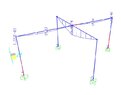
4 beams are supported by the column at one side, another side is jointed together at the intersection. I have assigned UDL of 20 kN/m on all the beams. 2 beams are longer (3m), 2 beams are shorter (2m) . Surprisingly, the BMD of the longer beams is hogging at the middle part , while the BMD of the shorter beams is sagging at the middle. Does it make sense.

Can someone explain this situation ? Why the BMD of the longer beam is hogging at the middle ? There's no column at the middle , how can there's hogging moment at the middle for the longer beam ?

I think the BMD of the shorter beam make sense and the BMD of the longer beam shall be thesame also (pure sagging in the middle and no sagging at all. ) Correct me if I am wrong ..
 

Attachments

  • 0008.JPG
    0008.JPG
    16.5 KB · Views: 107
Physics news on Phys.org
  • #2

Thank you for sharing your observations and questions about the behavior of the beams in your structure. I would like to offer some insights and explanations based on my knowledge and experience in structural engineering.

Firstly, it is important to understand that the behavior of beams is influenced by several factors such as loading, supports, and geometry. In your case, the beams are supported by a column on one side and are jointed together at the intersection on the other side. This type of support is known as a fixed support, which provides a significant amount of resistance to rotation and bending at the supported end.

Now, let's consider the loading on the beams. You have applied a uniform distributed load (UDL) of 20 kN/m on all the beams. This type of loading creates a constant shear force and a linearly varying bending moment along the length of the beam. It is important to note that the bending moment is directly proportional to the length of the beam. Therefore, the longer beams will experience a higher bending moment compared to the shorter beams.

Based on these factors, it is not surprising to see that the BMD of the longer beams is hogging at the middle while the BMD of the shorter beams is sagging at the middle. This is because the longer beams are experiencing a higher bending moment, which causes the beam to deflect downward in the middle. On the other hand, the shorter beams are experiencing a lower bending moment, which results in an upward deflection in the middle.

Furthermore, the presence of the column at one end of the beams also plays a role in the behavior of the beams. The fixed support provided by the column resists the rotation and bending of the beams, causing the BMD to change from a pure sagging moment to a hogging moment in the middle of the longer beams.

In conclusion, the behavior of the beams in your structure is a result of the combination of loading, supports, and geometry. The longer beams experience a higher bending moment due to their length and the fixed support at one end, resulting in a hogging moment at the middle. I hope this explanation helps to clarify the situation. Please feel free to ask if you have any further questions or concerns.Structural Engineer
 

1. What is BMD?

BMD stands for bending moment diagram. It is a graphical representation of the variation of bending moment along the length of a beam.

2. How do you determine the BMD of 4 beams joined at an intersection?

The BMD of 4 beams joined at an intersection can be determined by first analyzing each beam individually and then combining the individual BMDs at the intersection point. This can be done using the principles of statics and the equations of equilibrium.

3. What factors affect the BMD of 4 beams joined at an intersection?

The BMD of 4 beams joined at an intersection is affected by the loads applied to each beam, the material properties of the beams, and the geometry of the beams and their intersection point. Any changes in these factors can alter the BMD.

4. How does the BMD of 4 beams joined at an intersection impact the overall structural stability?

The BMD of 4 beams joined at an intersection is an important factor in determining the structural stability of a building or structure. It helps to identify potential weak points and areas of high stress, which can then be reinforced to ensure the overall stability of the structure.

5. Are there any software tools available to help analyze the BMD of 4 beams joined at an intersection?

Yes, there are several software tools available that can help with the analysis of the BMD of 4 beams joined at an intersection. These tools use mathematical algorithms and graphical representations to accurately determine the BMD and other structural properties, making it easier for engineers and scientists to design and analyze structures.

Similar threads

  • Special and General Relativity
Replies
10
Views
2K
Replies
6
Views
2K
  • Atomic and Condensed Matter
Replies
4
Views
6K
Replies
3
Views
3K
  • MATLAB, Maple, Mathematica, LaTeX
Replies
2
Views
2K
  • MATLAB, Maple, Mathematica, LaTeX
Replies
1
Views
3K
  • MATLAB, Maple, Mathematica, LaTeX
Replies
2
Views
3K
  • MATLAB, Maple, Mathematica, LaTeX
Replies
1
Views
2K
  • MATLAB, Maple, Mathematica, LaTeX
Replies
5
Views
3K
Back
Top