- #1
SoylentBlue
- 48
- 5
Thread moved from the technical forums to the schoolwork forums
- Homework Statement
- This is not a homework assignment. I am studying civil engineering by myself.
- Relevant Equations
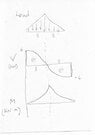
- Sum of the moments when you cut a beam, as shown above.
TL;DR Summary: A frame with a triangular distributed load is pin-connected to a 2-force member. Find the combined stress at point E on the frame.


I am stuck at determining the value of M at the cut. The book shows the value at 8.25KN-meter, but I cannot see how they arrived at that number.
Thank you in advance. I am trying to learn this on my own, so the Internet is my professor right now.
I am stuck at determining the value of M at the cut. The book shows the value at 8.25KN-meter, but I cannot see how they arrived at that number.
Thank you in advance. I am trying to learn this on my own, so the Internet is my professor right now.
Last edited: