- #1
garthenar
- 35
- 8
- Homework Statement
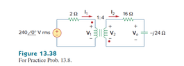
- 2. Use Cadence to simulate figure 13.38 in the book and the frequency is 10Hz. You need to plot (1) I1 and I2 in the same plot. (2) V0
Hint: 1. The voltage is amplitude, not AC magnitude
2. Ideal transformer is xfmr in Cadence
3. Use transient analysis
(See body for circuit)
- Relevant Equations
- Equations for ideal transformers.
V2 = nV1
I2 = (I1/n)
n = (N2/N1)
Here is the circuit...

Here is my work so far in cadence (I haven't put in values for other components in because the moment I saw the dot convention I started trying to figure that out).

Where I'm at
-There apparently isn't a way in Cadence Virtuoso (the program my class uses) to change the dot convention of the ideal transformer (xfmr in analoglib).
- Another student on the class discord said they "just flipped the right side of the circuit". I'm assuming they mean they flipped how that side is connected to the transformer.
- I went another route and decided to have a "negative" number of turns on my secondary coil to represent the alternate direction of the windings. The equations above work out to the right sign convention if I do this. (or at least I think).
I can't just run the simulation and pick the "best looking" result because I'm not familiar enough with transformers to know what I'm looking for.
At first I thought The other students method was completely wrong, but now that I look at it I think both methods might work. Though there's might be the best to go with because I don't know if the program will like that negative sign.
Any help would be appreciated.
Here is my work so far in cadence (I haven't put in values for other components in because the moment I saw the dot convention I started trying to figure that out).
Where I'm at
-There apparently isn't a way in Cadence Virtuoso (the program my class uses) to change the dot convention of the ideal transformer (xfmr in analoglib).
- Another student on the class discord said they "just flipped the right side of the circuit". I'm assuming they mean they flipped how that side is connected to the transformer.
- I went another route and decided to have a "negative" number of turns on my secondary coil to represent the alternate direction of the windings. The equations above work out to the right sign convention if I do this. (or at least I think).
I can't just run the simulation and pick the "best looking" result because I'm not familiar enough with transformers to know what I'm looking for.
At first I thought The other students method was completely wrong, but now that I look at it I think both methods might work. Though there's might be the best to go with because I don't know if the program will like that negative sign.
Any help would be appreciated.