Capstan Equation, Friction and Normal Force

  • Thread starter Oseania
  • Start date
  • Tags
    Friction
  • #1
Oseania
11
0
TL;DR Summary
How does capstan friction affect normal force
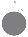
We have a following setup (see below). A plastic rod is placed inside a plastic ring. A wire is wrapped around a plastic rod from which it goes to the outer surface of the plastic ring. The friction coefficient between the wire and the plastic ring is about 0.1. We have several different sizes of plastic rods but the wire length always remains fixed. As such the endpoints of the wire change position according to plastic rod diameter (see second picture where points A and B have moved). In short, the smaller the diameter of plastic rod, the more we have wire in the outer ring.

We use the wire to pull the plastic rod against the inner surface of the ring. We measure the contact force F1 which is the force between the plastic rod and the inner surface of the ring. We would need to understand the relationship between F2 (the force between the wire and plastic rod) and F1 in different rod sizes.

I would assume that the friction between plastic ring and wire causes force to be lost due to capstan equation. That is, with smaller plastic rod we have more friction. As such I would assume that for given fixed force F1, the F2 varies according to the rod size? In other words we would achieve same force F1 with smaller F2 (and wire tension) with larger rods. :
Pic1.PNG
Pic2.PNG
 
Engineering news on Phys.org
  • #2
Oseania said:
The friction coefficient between the wire and the plastic ring is about 0.1.
Since the wire is crimped to the ring, the friction coefficient between the wire and the plastic ring cannot be important.

This looks like a gear pair, where the external circumference of the rod, drives the internal circumference of the ring.

Without tension in the wire, the rod will not drive the wire.
How do you maintain the initial tension in the wire?
 
  • #3
I had assumed they tension the wire and then crimp it somehow to keep said tension.
1696699914379.png


In that scenario do you think friction between the wire and the rings doesn't play a relevant role?
I'm still trying to come up with some equations. Maybe later I'll have something more interesting to show but it'd be nice to ensure I'm working in the right direction before putting more time into it. It's been forever since the last time I worked on a problem where capstain friction is a thing.

I'm realizing I'd first try to solve it for the case with no friction. I'm not sure it's trivial. @Oseania have you solved that simplified version of the problem?
 
Last edited:
  • #4
Are both points A and B attached to the ring, or is point A attached to a fixed object.
If A is fixed to the ground, then the wire forms a band brake which behaves like a directional clutch, that only allows rotation of the ring in one direction.
https://en.wikipedia.org/wiki/Band_brake

Where the wire slips off the ring, to pass around the rod, how come it does not continue to slip off the ring? If the rod was outside the ring, or guides were provided, that would not tend to happen.

At this stage, a better sketch of the device will be more helpful than equations.
 
  • #5
I'm not sure I understand what ##F_1## and ##F_2## are supposed to represent. To me, it looks like - if we do a free body diagram on the rod - they are two vertical forces, equal and opposite.

The capstan equation has to do with the tension in the wire and the forces at the end of that wire. I failed to see how this would change anything to the fact that ##F_2## is equal in magnitude to ##F_1##.

Or I misunderstand the problem.
 
  • #6
Juanda said:
View attachment 333204

I'm realizing I'd first try to solve it for the case with no friction.
I think it'd look like this:
1696702132742.png

If there's no friction then the tension in the wire will be uniform and equal to the external force applied on it so ##F=T_1=T_2##. From the geometry of the problem it is possible to obtain the value of ##F_1##.
If there is friction, then ##T_1## and ##T_2## won't be equal due to Capstan friction. However, I'd assume that the tension on the wire will tend to equalize as time and vibrations go on. I guess the equivalent uniform load could be obtained and the value could be recalculated again.
For example, during loading you will be able to preload it up to a certain point but not all the wire will reach the same tension due to friction so you'll be limited by the point at maximum stress. As time goes on, I believe the tension will tend to equalize so you might loose effective preload. The exact values would depend on the geometry of the problem.

Baluncore said:
At this stage, a better sketch of the device will be more helpful than equations.
That's probably right. We might be looking at the same image but seeing very different things in our heads.
I'll say though that I don't believe the rod or ring is turning. At least the OP didn't mention it so I don't see why the directional behavior of band brakes would apply here. I think it's just using the wire to push the rod against the ring.

Anyway, I'll hold the horses until OP provides some more context and pictures instead of babbling any longer.
 

Attachments

  • 1696701608301.png
    1696701608301.png
    3.2 KB · Views: 30
  • #7
Oseania said:
We measure the contact force F1 which is the force between the plastic rod and the inner surface of the ring. We would need to understand the relationship between F2 (the force between the wire and plastic rod) and F1 in different rod sizes.
@Juanda's sketch in Post #6 nicely shows the free body diagram (FBD). In the absence of friction or torque on rod, the two forces ##T_1## and ##T_2## are equal. If you know the angle of ##T_1## and ##T_2## relative to ##F_1##, then ##F_1## can be calculated from ##T_1## and ##T_2##, which are equal and equal to the tension in the wire. If the angles change with different rod sizes, then the force will change.

Oseania said:
TL;DR Summary: How does capstan friction affect normal force

friction between plastic ring and wire causes force to be lost due to capstan equation.
This implies (you do not clearly state) that you are driving the ring by rotating the rod. Rotating the rod causes the wire tension on one side to increase, and the tension on the other side to decrease. If everything is stiff enough that the angles of ##T_1## and ##T_2## do not change, then the increase in wire tension on one side is equal to the decrease in tension on the other side. The magnitude of the force ##F_1## with not change, but it's direction will. There will be a sideways force on the rod sufficient to make the sum of forces equal to zero.

As the torque on the rod increases, the low side wire tension will decrease until the rod spins in the wire (capstan equation).
 
  • #8
I understand that I might have oversimplified the problem a bit. Mechanically what happens in the device:
1. The plastic rod placed inside the wire (see figure 1).
2. The positions A and B are moved so that the wire is tight. Now, these positions depend on the rod diameter.
3. When wire is tight, we heat the wire (it is shape memory alloy) which causes it to shrink a bit. This further tightens the wire around the plastic rod. The wire slides so that the excess slack is taken out. Note; the positions A and B remains fixed in the ring body.
4. We measure the contact force F1.

We suspect that the for given contact force F1 (e.g. 10N) the other contact force F2 varies depending on the rod size. That is, it is not 10N but something else depending rod size. We suspect that this causes some issues in our setup.
 
  • #9
Oseania said:
I understand that I might have oversimplified the problem a bit. Mechanically what happens in the device:
1. The plastic rod placed inside the wire (see figure 1).
2. The positions A and B are moved so that the wire is tight. Now, these positions depend on the rod diameter.
3. When wire is tight, we heat the wire (it is shape memory alloy) which causes it to shrink a bit. This further tightens the wire around the plastic rod. The wire slides so that the excess slack is taken out. Note; the positions A and B remains fixed in the ring body.
4. We measure the contact force F1.

We suspect that the for given contact force F1 (e.g. 10N) the other contact force F2 varies depending on the rod size. That is, it is not 10N but something else depending rod size. We suspect that this causes some issues in our setup.

Context helps. You might think you're making it simpler by not talking about surrounding details but it often results in the opposite. Maybe you did it to keep some confidential stuff from your work as low profile as possible which I understand so no worries. There are actually multiple things from my job I'd love to discuss here and I always struggle about how to do it without exposing anything that could be a problem.

Now, back to the problem at hand. Like @jack action said in #5, the forces ##F_1## and ##F_2## will be equal. They must be so the plastic rod is in equilibrium and that fact does not depend on the geometry of the ring and rod. That's assuming both forces are aligned by the way.
Also, ##F_2## will be the resultant force from the contact between the wire and the rod. It's more like a pressure and that's the resultant force from the pressure along the contact area. The same goes on with ##F_1## but that looks more like a "contact point" although it'll also deform creating a pressure area that has an equivalent force associated with it.

What I think you need is to find out how the tension of the wire is related to the forces ##F_1## and ##F_2##. That's what I was aiming at with what I posted on #6.
In that scenario, the geometry will affect the contact forces because different rods will cause different angles.
Since you have experimental results to compare with, I'd recommend you solve the contact force as a function of the tension in the wire and the diameter of the rod considering there is no friction at all. If the results differ significantly then it suggests that either you didn't solve the problem correctly or that friction is actually something you need to add to the model. If you have doubts, maybe you can use some lubricant to reduce friction and compare the experimental results with your model too, or check if lubrication changes the force ##F_1## you can experimentally measure.
 
  • Like
Likes jack action
  • #10
Oseania said:
...
We suspect that the for given contact force F1 (e.g. 10N) the other contact force F2 varies depending on the rod size. That is, it is not 10N but something else depending rod size. We suspect that this causes some issues in our setup.
How are you actually measuring F2?
Please, see:
https://www.engineeringtoolbox.com/bollard-force-d_1296.html
 
  • #11
This is an impossible topology.
Any tension in the wire, will pull the wire over the edge, and off the outside of the ring.
 
  • #12
Baluncore said:
This is an impossible topology.
Any tension in the wire, will pull the wire over the edge, and off the outside of the ring.
I can't see what you mean. OP said this is an actual experimental setup he's working on. How could it be impossible?
I'm imagining the "ring" more like a tube. It's true that if the "ring" is not long enough, the wire will just be impossible to tension as you said.

Maybe OP can share a picture of the real setup next to the diagram to clear the confusion or something similar.
 
  • #13
Baluncore said:
This is an impossible topology.
Any tension in the wire, will pull the wire over the edge, and off the outside of the ring.
No, it is not impossible topology. We cannot share images of the actual device but it is pretty much wrapping a wire around a plastic rod, and then attaching those wires to a "ring". Of course you need to have grooves in the ring to guide the wires etc. but they are not important to the forces and tensions.

We are now conducting new measurements which hopefully allows us to understand better how capstan friction plays part.
 
  • #14
Juanda said:
Context helps. You might think you're making it simpler by not talking about surrounding details but it often results in the opposite. Maybe you did it to keep some confidential stuff from your work as low profile as possible which I understand so no worries. There are actually multiple things from my job I'd love to discuss here and I always struggle about how to do it without exposing anything that could be a problem.

Now, back to the problem at hand. Like @jack action said in #5, the forces ##F_1## and ##F_2## will be equal. They must be so the plastic rod is in equilibrium and that fact does not depend on the geometry of the ring and rod. That's assuming both forces are aligned by the way.
Also, ##F_2## will be the resultant force from the contact between the wire and the rod. It's more like a pressure and that's the resultant force from the pressure along the contact area. The same goes on with ##F_1## but that looks more like a "contact point" although it'll also deform creating a pressure area that has an equivalent force associated with it.

What I think you need is to find out how the tension of the wire is related to the forces ##F_1## and ##F_2##. That's what I was aiming at with what I posted on #6.
In that scenario, the geometry will affect the contact forces because different rods will cause different angles.
Since you have experimental results to compare with, I'd recommend you solve the contact force as a function of the tension in the wire and the diameter of the rod considering there is no friction at all. If the results differ significantly then it suggests that either you didn't solve the problem correctly or that friction is actually something you need to add to the model. If you have doubts, maybe you can use some lubricant to reduce friction and compare the experimental results with your model too, or check if lubrication changes the force ##F_1## you can experimentally measure.
Now I started to think that as people have said the forces F1 and F2 have to be equal naturally. However, would the pressure distribution on the plastic rod depend on the rod diameter?
 
  • #15
Oseania said:
Now I started to think that as people have said the forces F1 and F2 have to be equal naturally. However, would the pressure distribution on the plastic rod depend on the rod diameter?
I'd say yes. The diameter will be related to the angles of ##T_1## and ##T_2## (look at post #6). It'll also change the amount of surface contacting the wire.

I maintain I would proceed as explained in #9. This is:
Juanda said:
Now, back to the problem at hand. Like @jack action said in #5, the forces ##F_1## and ##F_2## will be equal. They must be so the plastic rod is in equilibrium and that fact does not depend on the geometry of the ring and rod. That's assuming both forces are aligned by the way.
Also, ##F_2## will be the resultant force from the contact between the wire and the rod. It's more like a pressure and that's the resultant force from the pressure along the contact area. The same goes on with ##F_1## but that looks more like a "contact point" although it'll also deform creating a pressure area that has an equivalent force associated with it.

What I think you need is to find out how the tension of the wire is related to the forces ##F_1## and ##F_2##. That's what I was aiming at with what I posted on #6.
In that scenario, the geometry will affect the contact forces because different rods will cause different angles.
Since you have experimental results to compare with, I'd recommend you solve the contact force as a function of the tension in the wire and the diameter of the rod considering there is no friction at all. If the results differ significantly then it suggests that either you didn't solve the problem correctly or that friction is actually something you need to add to the model. If you have doubts, maybe you can use some lubricant to reduce friction and compare the experimental results with your model too, or check if lubrication changes the force ##F_1## you can experimentally measure.
 

What is the Capstan Equation?

The Capstan Equation, also known as the Euler-Eytelwein formula, describes the relation between the tensions on either side of a rope or cable that is wrapped around a cylinder or capstan. It is expressed as T1 = T2 * e^(μθ), where T1 is the tension on the side where the rope is being pulled, T2 is the tension on the other side, μ is the coefficient of friction between the rope and the capstan, and θ is the angle of contact in radians.

How does friction affect the Capstan Equation?

Friction plays a crucial role in the Capstan Equation. The coefficient of friction, μ, determines how effectively the tension can be increased as the rope wraps around the capstan. Higher friction coefficients result in a greater difference between T1 and T2, allowing for a larger load to be supported by a smaller input force. The friction essentially allows the capstan to 'grip' the rope, preventing slippage and enabling the transfer of tension.

What is normal force in the context of the Capstan Equation?

In the context of the Capstan Equation, the normal force is the force exerted by the surface of the capstan against the rope. This force is perpendicular to the surface of contact and is crucial for generating friction. The normal force must be sufficient to prevent the rope from slipping, which is directly influenced by the load on the rope and the characteristics of the capstan's surface.

How can the Capstan Equation be applied in real-world scenarios?

The Capstan Equation is widely used in scenarios where ropes are used to manage loads, such as in sailing, climbing, and the use of pulleys in mechanical systems. For example, it helps in designing the amount of wrap and the type of material needed for ropes on winches and capstans to ensure that there is enough friction to hold and manipulate heavy loads safely.

What factors can alter the effectiveness of the Capstan Equation?

Several factors can alter the effectiveness of the Capstan Equation, including the material and condition of the rope and capstan, the amount of contact angle (θ), environmental conditions like moisture and dirt, and the evenness of the load distribution. All these factors can affect the coefficient of friction (μ) and the normal force, thereby influencing the tension relationship described by the Capstan Equation.

Similar threads

  • Mechanical Engineering
Replies
5
Views
286
  • Mechanical Engineering
Replies
4
Views
857
  • Mechanical Engineering
Replies
9
Views
2K
Replies
5
Views
2K
  • Mechanical Engineering
Replies
8
Views
1K
  • Electrical Engineering
Replies
2
Views
421
Replies
4
Views
671
  • Introductory Physics Homework Help
Replies
5
Views
903
Replies
4
Views
289
  • Sci-Fi Writing and World Building
Replies
30
Views
2K
Back
Top