- #1
OSR
- 17
- 4
- TL;DR Summary
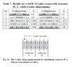
- Phase Arrangement of Parallel Medium-Voltage Cables
Hi
If the length of parallel medium-voltage cable runs is approximately 20 meters, and cable sheath is grounded only at one end, does it matter how the parallel phases are installed on the cable rack? If the straightforward installation method doesn't follow the rule for arranging the phases on the rack correctly, is there any significance to it in terms of cable load capacity or any other aspect?"

If the length of parallel medium-voltage cable runs is approximately 20 meters, and cable sheath is grounded only at one end, does it matter how the parallel phases are installed on the cable rack? If the straightforward installation method doesn't follow the rule for arranging the phases on the rack correctly, is there any significance to it in terms of cable load capacity or any other aspect?"