Create a Phasor Diagram Easily: Step-by-Step Guide & Helpful Tips

In summary, the conversation discusses how to create a phasor diagram for a synchronous induction motor. The power factor and stator reactive voltage drop are calculated from the network point of view, with the current being 43.475 A and leading the phase-to-phase voltage by 36.87 degrees. The voltage drop is equal to IA*[cosφ+jsinφ]*jXs, with the reactive part being jIA*cosφ*Xs.
  • #1
Cassy85
1
0
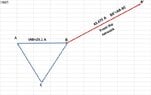
Hi, I'm struggling to find out how to create a phasor diagram. I have attached a photo of the question any help would be greatly appreciated.
Screenshot_20211003-194735.png

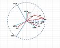
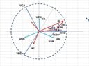
This is what I have attempted so far.
It's question 2b I am really struggling with.
I'm not looking for the answers just looking for some direction.

  1. Calculate phase current
Phase current = 250003 x 415 x 0.8
Phase current = 25.1 Amps
cos-10.8=36.87
I = 25.1 ∠36.87° Amps
  1. Calculate the stator reactive voltage drop IXs

Voltage drop = IaXs
25.1 x 4 ∠36.87° + 90°
Voltage drop (IXs) = 100.4 ∠126.87° volts
 
Physics news on Phys.org
  • #2
First no such motor "synchronous induction motor" does exist .Since the power factor is leading it is about synchronous motor when the excitation current is more than rated.
The motor has an a.c. winding in stator part and a d.c. winding [poles] on the rotor. Since it is a separately E noted, the generated voltage is equal to supply voltage.
The generated voltage has to be in the load case.
If the power mentioned is "input power" the apparent power it is the ratio 25/0.8.
overexcited synchronous motor phasor diagram.jpg

The loaded current it is 25000/0.8/√3/415=43.475 A
 
  • #3
Actually this is the current from the network. The current in the motor winding in triangle it is only 25.1A, indeed.
 

Attachments

  • Triangle currents.jpg
    Triangle currents.jpg
    27.3 KB · Views: 107
  • #4
In my opinion, the power factor and Xs are calculated from the network point of view so for an equivalent star motor. In this case the current IA= 43.475 A and is leading the phase-to-neutral voltage VAN with φ= 36.87 degrees. Then the voltage drop [total] is IA*[cosφ+jsinφ]*jXs and the reactive part is jIA*cosφ*Xs.
 
  • #5
The vectorial diagram it could be like this one:
 

Attachments

  • synchronous motor vectorial diagram.jpg
    synchronous motor vectorial diagram.jpg
    48.4 KB · Views: 103
  • #6
My mistake. The voltage considered for equivalent motor is not
“the leading the phase-to-neutral voltage” as I said but the phase-to-phase voltage. So, the vectorial diagram on the trigonometric circle it has to be like this:
 

Attachments

  • synchronous motor vectorial diagram.jpg
    synchronous motor vectorial diagram.jpg
    44.9 KB · Views: 100

1. What is a phasor diagram?

A phasor diagram is a graphical representation of a sinusoidal signal in the time domain and its corresponding vector in the frequency domain. It is commonly used in electrical engineering and physics to analyze the amplitude and phase relationships between different components of a signal.

2. Why is it important to create a phasor diagram?

Creating a phasor diagram allows for a visual representation of a complex signal, making it easier to analyze and understand. It also helps in identifying the amplitude and phase relationships between different components of the signal, which is crucial in circuit analysis and troubleshooting.

3. How do I create a phasor diagram?

To create a phasor diagram, you will need to have the amplitude and phase information of the different components of the signal. Then, you can use a scale to represent the amplitude and angle to represent the phase on a 2-dimensional graph. The vectors can be drawn using these values, and the resulting diagram will show the magnitude and phase relationships between the components.

4. What are some helpful tips for creating a phasor diagram?

Some helpful tips for creating a phasor diagram include using a consistent scale for all the components, labeling the vectors and angles, and using different colors for each component to make it easier to differentiate. It is also important to double-check the calculations and make sure they are accurate before drawing the diagram.

5. Can I use software to create a phasor diagram?

Yes, there are many software programs available that can help you create a phasor diagram easily. These programs allow you to input the values of the different components and automatically generate the diagram for you. They also have features such as labeling, color-coding, and scaling, making it even more convenient and accurate to create a phasor diagram.

Similar threads

  • Engineering and Comp Sci Homework Help
Replies
3
Views
2K
  • Engineering and Comp Sci Homework Help
Replies
2
Views
2K
  • Engineering and Comp Sci Homework Help
Replies
4
Views
2K
  • Engineering and Comp Sci Homework Help
Replies
4
Views
3K
  • Engineering and Comp Sci Homework Help
Replies
2
Views
4K
  • Introductory Physics Homework Help
Replies
4
Views
5K
  • Introductory Physics Homework Help
Replies
2
Views
8K
Back
Top