Equation for the angular position of a slider crank mechanism

In summary, the equation for the angle between Vb and Vb' can be found by first calculating the angle of γ and using the summation towards the 180 degrees.
  • #1
Mech_LS24
148
16
TL;DR Summary
I can't figure out how to setup a equation for the angle position of a slider crank mechanism. As the mechanism is driven by an angular velocity, the angle (theta) changes constantly. Theta is the angle which rotates the crank. I would like find the angle α (alpha) during the rotation of crank.
Hi!

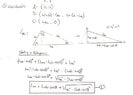
I would like to know how I could define an equation for α with given the two lengths of the rods and angle theta (θ). I sketched the situation below, the problem arises when the rod Lab has pasts the 180 degrees.

Like to hear.

Slider_crank_mechanism.jpg
 
Engineering news on Phys.org
  • #2
It seems
[tex]\alpha+\gamma+2\pi-\theta_2=\pi[/tex].
 
Last edited:
  • #3
anuttarasammyak said:
It seems
α+γ+2π−θ2=π.
For θ2 you are correct (angles in radians). But using the same formula for θ1 doesn't work.

I would like to use θ as input in a worksheet, therefore one formula is demanded. So, the input will be angles between 0 and 360 degrees. When is larger as 180 there should be added a minus sign in the formula, this is what I want to avoid. But I can't figure out that formula because I get the errors with + and - signs which is also seen here with this formula.
 
  • #4
If you want common equation for ##\theta_1## and ##\theta_2 ## you should set up a systematic rule to measure all the angles like ##\theta_1## and ##\theta_2## are both measured counterclockwise from x axis. In your figure I see two ##\alpha## angles and two ##\gamma## angles. In which way of measuring rule these angles show these same values ?
 
  • #5
What do you mean with systematic way? I got two constants, Lab and Lbc, the two rod which moves the 'piston'. That should be used for the input of the angles?

In your post I see red text with yellow background?
 
  • #6
I mean
How do you define ##\angle ACB## for B upside and B downside ?
How do you define ##\angle ABC## for B upside and B downside ?
How do you define ##\angle CAB## for B upside and B downside ?
 
  • #7
Sorry, you're right, I am going to draw it. Please give me a moment
 
  • #8
The sketches below is what I mean. In situation 2, I need to add an α' for getting the right γ-angle.

I changed the definitions of the angles, to correspond with the Law of sinus.

Slider_crank_mechanism (1).jpg

Slider_crank_mechanism_01.jpg
 
  • #9
Do you mean same equation holds for the same two angles and large / small ##\alpha## ?
 
  • Like
Likes Mech_LS24
  • #10
anuttarasammyak said:
Do you mean same equation holds for the same two angles and large / small ##\alpha## ?
Yes, I need angle β for calculating the velocity for rod Lbc.
 
  • #11
Maybe this sketch gives a better indication. I need to know the angle between Vb (velocity of the rod) and Vb (tangent velocity of rod AB, so perpendicular with rod AB). This angle is depended on the input angle θ.

Could you help me with finding an equation for that?

Slider_crank_mechanism_02.jpg
 
  • #12
Though it might be not along your way, an analytic way is by introducing xy coordinate
[tex]A(0,0)[/tex]
[tex]B(L_{AB}\cos\theta,L_{AB}\sin\theta)[/tex]
[tex]C(L_{AC}(\theta),0)[/tex]
and the equation is
[tex](L_{AC}(\theta)-L_{AB}\cos\theta)^2+L_{AB}^2\sin^2\theta=L_{BC}^2[/tex]
[tex]L_{AC}(\theta)=L_{AB}\cos\theta+\sqrt{L_{BC}^2-L_{AB}^2\sin^2\theta}[/tex]
The velocity of rod is
[tex]\frac{d}{dt}L_{AC}(\theta)=\frac{d}{d\theta}L_{AC}(\theta)\ \ \dot{\theta}[/tex]
 
Last edited:
  • Like
Likes Mech_LS24
  • #13
Thanks,

What makes the x-coordinate of C the formula below? Shouldn't it not just be Lac?
[tex]C(L_{AC}(\theta),0)[/tex]

And the equation should be without the squares under the root, like below?:
[tex]L_{AC}(\theta)=L_{AB}\cos\theta+\sqrt{L_{BC}-L_{AB}\sin\theta}[/tex]

For example:
3^2 = 5^2 - 4^2
3 = sqrt((5^2) - (4^2)) doesn't make sense.

And, how to get that angle at point B in a single equation?

How did you come to that velocity differential equation? Could you give an example how to differentiate that velocity?
 
  • #14
Mech_LS24 said:
Shouldn't it not just be Lac?
I wrote it to make it clear that it is a function of ##\theta##.

Imagine what happens in your sketch when you choose minus sign.

##L_{AC}## given, you can get ##\angle ABC## by sine law.

##\frac{df(x)}{dt}=\frac{df}{dx}\frac{dx}{dt}## is the formula used. ##L_{AC}## is a function of ##\theta## and ##\theta## is a function of time.
 
Last edited:
  • Like
Likes Mech_LS24
  • #15
anuttarasammyak said:
I wrote it to make it clear that it is a function of θ.
👍, I just wanted to be sure.

anuttarasammyak said:
LAC given, you can get ∠ABC by sine law.

df(x)dt=dfdxdxdt is the formula used. LAC is a function of θ and θ is a function of time.
Good point, I am going to draw and calculate on scale for different situations later today, thanks!
 
  • #16
I have made the drawings on scale (with 4 different positions) and written the calculation for Lac as well. I ended up with the same equation as you for the length of Lac, so I do understand it. But I am issuing two problems now:
  1. With the law of sines I end up with two solutions, where 99.7 degrees should be the right outcome. The only way I could find that angle is by first calculation the angle of γ and use the summation towards the 180 degrees.
  2. An equation for the angle between Vb and Vb' is still hard to determine. As I have the issue that using 90 degrees as reference would result in minus values (see situation 2, on the page with the main sketches upper right).

Hopefully you get the message, I tried my best for the sketches and approaches towards the equations/calculations.

*Afterwards, I will look at the differential equation. I have some documentation about it now, so going to read that :)

Slider_crank.jpg

Slider_crank_02.jpg
 

Attachments

  • Slider_crank_01.jpg
    Slider_crank_01.jpg
    32.2 KB · Views: 151
  • #17
Mech_LS24 said:
An equation for the angle between Vb and Vb' is still hard to determine. As I have the issue that using 90 degrees as reference would result in minus values (see situation 2, on the page with the main sketches upper right).
The angle you say seems ##\angle ABC## - ##\pi/2## where
[tex]\angle ABC = \sin^{-1} [\frac{L_{AB}\cos\theta+\sqrt{L_{BC}^2-L_{AB}^2\sin^2\theta}}{L_{BC}}\ sin\theta\ ][/tex]
Do you have a problem of its sign ?
 
Last edited:
  • #18
You are right, I managed it to plot it in Excel, see result below.

Thanks for your help and active participation! :)
1628187469379.png
 
  • Like
Likes anuttarasammyak
  • #19
Mech_LS24 said:
You are right, I managed it to plot it in Excel, see result below.

Thanks for your help and active participation! :)
View attachment 287140
I got the sam task as homework, but I am stuck in excel because of the negative values under the root..How did you manage to solve it?
 
  • #20
Bence2002 said:
I got the sam task as homework, but I am stuck in excel because of the negative values under the root..How did you manage to solve it?
The value under the root cannot be negative, it is a design constraint.

The only way it can be negative is if ##L_{AB} \gt L_{BC}##. If that is the case, when ##AB## is at 90° with the cylinder ##AC##, the link ##BC## wouldn't be long enough to reach the cylinder. The mechanism would therefore bind before reaching that point.
 
  • #21
jack action said:
The value under the root cannot be negative, it is a design constraint.

The only way it can be negative is if ##L_{AB} \gt L_{BC}##. If that is the case, when ##AB## is at 90° with the cylinder ##AC##, the link ##BC## wouldn't be long enough to reach the cylinder. The mechanism would therefore bind before reaching that point.
Thank you!
I managed to solve it later, I made a stupid mistake 😅
It's all good now :)
 
  • Like
Likes jack action

1. What is a slider crank mechanism?

A slider crank mechanism is a mechanical linkage that converts rotational motion into reciprocating motion, or vice versa. It is commonly used in engines, pumps, and other machinery.

2. What is the equation for the angular position of a slider crank mechanism?

The equation for the angular position of a slider crank mechanism is θ = ωt + θ0, where θ is the angular position, ω is the angular velocity, t is time, and θ0 is the initial angular position.

3. How is the equation for the angular position derived?

The equation for the angular position of a slider crank mechanism is derived from the geometry of the mechanism, specifically the lengths of the crank and connecting rod, and the angle of the crank.

4. What factors can affect the angular position of a slider crank mechanism?

The angular position of a slider crank mechanism can be affected by the length of the crank and connecting rod, the angle of the crank, the angular velocity, and any external forces or torques acting on the mechanism.

5. Can the equation for the angular position be used to predict the motion of a slider crank mechanism?

Yes, the equation for the angular position can be used to predict the motion of a slider crank mechanism as long as the initial conditions and external forces are known.

Similar threads

Replies
7
Views
2K
Replies
7
Views
3K
  • Mechanical Engineering
Replies
13
Views
2K
  • Engineering and Comp Sci Homework Help
Replies
6
Views
3K
  • Mechanical Engineering
Replies
3
Views
12K
  • Mechanical Engineering
Replies
2
Views
3K
Replies
9
Views
2K
Replies
10
Views
2K
  • Mechanical Engineering
Replies
2
Views
2K
Replies
8
Views
3K
Back
Top