- #1
JackLee
- 8
- 1
- TL;DR Summary
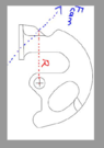
- Torque adjustment due to custom extension. Force Transmitted by torque at an angle.
A torque meter with a triangular slab extension is inserted into a corresponding triangular slot. The C-shaped arm features a V-shaped dent on which a roller is seated. This roller is held in compression by a spring. The roller's positions are labeled '0' for the initial state and '1' for the final state. The torque meter reads 40 in-lb when transitioning from state 0 to state 1. My goal is to determine the force exerted on the spring during this transition.
My current thought process:
Concerning the torque reading, if the extension length from the torque wrench socket to pivot A is 1.5 inches, does this mean that the actual torque applied at point A is 46 in-lb? The highlighted length represents the extension/adaptor.


My current thought process:
- Find the lever arm distance 'r', this includes the extension length. assume r= 7.5''
- M = r X F, F = 5 lbs, this is the force applied at the torque meter.
- Then, using the pressure angles, I think there is a way to determine the force component acting in the direction of the spring. This is the step that I am really confused at.
Concerning the torque reading, if the extension length from the torque wrench socket to pivot A is 1.5 inches, does this mean that the actual torque applied at point A is 46 in-lb? The highlighted length represents the extension/adaptor.