How to rig multiple IR2103 to form an H-bridge to excite transformer

  • Thread starter checkmatescott
  • Start date
  • Tags
    Arduino
In summary, the OP is trying to design a machine that puts out a constant current, and wants to put it through an H-bridge setup to reverse the polarity at 50hz. After that, the 55v at 50hz will excite a transformer with a turn ratio of 4.182 to achieve an approximate 230v ac.
  • #1
checkmatescott
80
2
TL;DR Summary
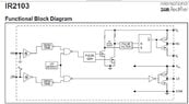
I need to know how to ocsillate the current between +55v and reverse. I have been advised to use multiple IR2103 half bridge drivers in conjunction with an arduino and 4 digital pins need the guidence to setup this circuit. Can anybody help. The more help I get the easier it is to understand the manual!
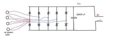
I am designing a machine that puts out constant ,and I want to put it through an H-bridge style setup to reverse the polarity at 50hz, by utilising IR2103 half-bridge's and arduino. after hat the 55v at 50hz will excite a transformer with turn ration 4.182 to achieve approximately 230v ac. thanks for any help in advance!
 
Engineering news on Phys.org
  • #2
230 volts is a high and lethal voltage. If you cannot read and understand the manufacturer's datasheet, then you lack the experience and training necessary to safely implement the circuit.
 
  • Like
Likes DaveE
  • #3
Well then talk me through It, its not like im going to hold some guy on the internet accountable, for some help and advice he gave me. I just want to know how to oscillate 55v at 50hz! its for my project and btw i wear rubber gloves
 
  • #4
At the end of the day its a chip with 8 pins surely it cant be that hard to explain the operation. treat explaining to me as a challenge and don't think about the ethics ie "its too high of a voltage for him to handle or understand, it could be dangerous"
 
  • #5
For any help, I would be forever in your debt and will appreciate it a lot.
 
  • #6
Unless it's too difficult for you to explain.
 
  • #7
checkmatescott said:
... its not like im going to hold some guy on the internet accountable, ...
This website has rules, against dangerous activities, to protect this website.

I am not prepared to assist you in your attempt at gaining a Darwin Award.

Go to college and study. Train to qualify as an electrician or an engineer.

Find out why your other thread was paused.
 
  • #8
The part I need comes before the transformer and is therefore not dangerous
 
  • #9
I can see that you don't want to part with your knowledge. I understand the not gates and nor gates I don't know what UV means and I don't know what dead time means. I understand the pulse generation and how it works, I understand the internal transistors and I understand the pulse filter, so there's alot I do get. I just need some help I have a gcse in electronics and a level 3 diploma in electrical and mechanical engineering. and ok another approach can you tell me where I can get the information I need that explains how to get the desired ac at 50hz 50% duty cycle
 

Attachments

  • IR2103 FBD.jpg
    IR2103 FBD.jpg
    34.3 KB · Views: 52
Last edited:
  • #10
checkmatescott said:
The part I need comes before the transformer and is therefore not dangerous
One thing leads to another.

You are clearly inexperienced, and are not in a position to assess the danger.
https://en.wikipedia.org/wiki/Dunning–Kruger_effect

Why do you not simulate the circuit with LTspice?

A transformer with a turns-ratio of 4.182 would have too many turns and too much resistance. 500 : 2091 = 4.182
 
  • #11
alternating 55v on a coil with 1:4.182 the output will be around 230v i need 55v ac 50hz 50% duty cycle. ok I will attempt to use LTSpice but i need the
 
  • #12
because 55 * 4.182 = 230.01
 
  • #13
ok so another approach can i just BUY an inverter that takes an input of 55v?
 
  • #14
There is still an elephant in the room.

How much current can you draw from the 55 volt supply before the voltage falls below 50 volts?

You need to know that before designing or buying an inverter.
 
  • #15
ok I next go to work on it for 2 hours on friday. I have two meters, my four coils are connected to a 10 diode bridge similar to this. I still need to do that check, I will be using two multi meters at the same time one measuring votage accross the output, and the other in-line with a power resistor of 27 ohm 100w to give current reading and I do realise that if I dont want to blow the power resistor i can only run it up to 50v because 50/27=1.185185 and then for power multiply current by voltage eg 1.185185*50 which equals to 92.approximatly, I think max I can do it 52v, but in reality when I tested for current, I was getting up to 70 amps, so yeah I need to the voltage check on one multimeter and current showing on the other at the same time, cheers
 

Attachments

  • 10 diode bridge.jpg
    10 diode bridge.jpg
    15.4 KB · Views: 44
Last edited:
  • #16
and ok say i find this time that the voltage drops from 55 to 50, then what procedure do I do to choose something adequit ? method?
 
  • #17
Baluncore said:
Find out why your other thread was paused.
@checkmatescott -- It is against the PF rules to try to reopen a locked thread. This thread here is also on pause. I will answer your PM about the first thread later today.
 
  • #18
berkeman said:
@checkmatescott -- It is against the PF rules to try to reopen a locked thread. This thread here is also on pause. I will answer your PM about the first thread later today.
After a long PM conversation, the OP will not be returning to PF. I mention why at the end of his original thread on these questions. Have a nice day.
 
  • Like
Likes Bystander

1. How many IR2103 chips do I need to form an H-bridge for a transformer?

The number of IR2103 chips needed will depend on the voltage and current requirements of your transformer. Typically, one IR2103 chip can handle up to 600V and 2A, so you will need at least two chips to form an H-bridge for a transformer. However, for higher voltage and current requirements, you may need to use more chips.

2. How do I connect the IR2103 chips to form an H-bridge?

To form an H-bridge, you will need to connect the input pins (IN1 and IN2) of one IR2103 chip to the output pins (OUT1 and OUT2) of the other chip. Then, connect the input pins of the other chip to the output pins of the first chip. This will create a complete circuit for the H-bridge.

3. What is the purpose of using an H-bridge to excite a transformer?

An H-bridge is used to control the direction and magnitude of current flow through a transformer. By switching the input signals to the IR2103 chips, the H-bridge can create a pulsating magnetic field that will excite the transformer and produce an AC output.

4. Can I use any transformer with an H-bridge and IR2103 chips?

No, you should choose a transformer that is compatible with the voltage and current ratings of the IR2103 chips. Additionally, the transformer should have a suitable turns ratio to match the input and output voltage requirements of your circuit.

5. Are there any safety precautions I should take when using an H-bridge and IR2103 chips to excite a transformer?

Yes, it is important to follow proper safety precautions when working with high voltage and current circuits. Make sure to use appropriate insulation and protective gear, and always double check your connections before powering on the circuit. It is also recommended to use a fuse or circuit breaker to protect against potential short circuits.

Back
Top