Method of mirroring - metal plates

  • #1
JoelKTH
29
1
Homework Statement
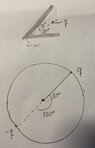
Two large metal plates form a 60-degree angle with each other. On the bisector of the angle at a distance a from the apex, there is a point charge q. Determine the force on the charge!
Relevant Equations
$F = qE$
\(E = \frac{q(r - r')}{4\pi\epsilon_0 |r - r'|^3}\)
Hi,

I'm having some trouble understanding how to solve this problem. I have a few questions:

1. I understand that I need to make an educated guess for the electric potential, where \(V_1\) is given by:

V_1 = \frac{q}{4\pi\epsilon_0} \left(\frac{1}{r_1} - \frac{1}{r_2} + \frac{1}{r_3} - \frac{1}{r_4} + \frac{1}{r_5} - \frac{1}{r_6}\right) V_2 Is this guess chosen because it satisfies \(\nabla^2 V_1 = 0\)? Is this due to the fact that \(V_2\) at the metal plate has no potential? Could you explain the reasoning behind this educated guess? Also, I am a bit confused as for when \(V_1\) becomes significant close to the real charge, why is \(r_1 \rightarrow 0\)? Can you elaborate on this point? I know that \(V_1 = V_2\) at the boundary, but I'm not entirely clear on how the educated guess applies in this context.

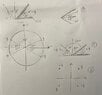
2. According to the figure, the electric field in the air from the real surface charge is the same as the electric field from the 5 fictive mirror charges. How can I determine the geometry of these fictive charges? In simpler cases, like planes, I understand that if there is a positive charge \(q\) followed by a metal surface, I can place a fictitious charge of \(-q\) below and calculate the electric field. However, given the complex symmetry in this problem, I'm quite lost. How can I set up this problem correctly?

3. I've attached two pictures illustrating how the solution gives me a tip for how the problem behaves, but I have some uncertainties there.

4. When I attempt to find the distance between \(q\) and the fictive charges using the method of mirroring, I get confused.

Finally, I'm aware that \(F = qE\).
I try to calculate the electric field \(E = \frac{q(r - r')}{4\pi\epsilon_0 |r - r'|^3}\) first.
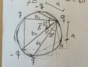
Try to find the E-field and do superposition. First I need to know the distances. I have attached my thinking.

\[
\tan(30^\circ) = \frac{q}{b_1} \rightarrow b_1 = \frac{a}{\tan(60^\circ)} = \sqrt{3}a
\]

\[
\sin(60^\circ) = \frac{q}{b_2} \rightarrow b_2 = \frac{a}{\sin(60^\circ)}
\]

\[
\cos(30^\circ) = \frac{a}{b_3} \rightarrow b_3 = \frac{a}{\cos(30^\circ)} = \frac{a}{\sqrt{3}/2} = \frac{2a}{\sqrt{3}}
\]

\[
E = \frac{q(r - r')}{4\pi\epsilon_0 |r - r'|^3}
\]

Any insights or guidance you can provide would be greatly appreciated.
 

Attachments

  • C5Q6.jpg
    C5Q6.jpg
    32.4 KB · Views: 35
  • C5Q6add.jpg
    C5Q6add.jpg
    61.3 KB · Views: 35
Last edited:
Physics news on Phys.org
  • #2
JoelKTH said:
I understand that I need to make an educated guess for the electric potential
Not so. This is all about the method of images. Your task is to figure out how to place a few point charges, replacing the metal plates, such that the field within the 60° sector bounded by the plates is unchanged. I.e. the new point charges create the same field in that region that the induced charges in the metal plates create.
(Since the plates are described as large, compared with a presumably, you can consider them grounded.)
Hint: if the plates were mirrors, where would the images of the point charge be?
 
Last edited:
  • Like
Likes JoelKTH
  • #3
Yes, but are those two requirements not for using the method of images? As you say they might not be needed to solve the actual problem.

Judging from the method of images and my knowledge, my first step would be to place a negative charge -q 180° from the point charge. See image attached. Not sure about if this is the first point charge to be placed. But the potential at the metal plates are not 0 right now. I understand that the other charges needs to be placed too, as the metal plate is bounded by 60°. What would be a good process to find where the point charges should be placed?
 

Attachments

  • C5Q6fig.jpg
    C5Q6fig.jpg
    28.2 KB · Views: 26
  • #4
JoelKTH said:
What would be a good process to find where the point charges should be placed?
As I wrote, treat them as mirrors. Where would the image be from one mirror? Where from the other? Where would the secondary images of those images be?…
Note that each reflection switches the sign on the image charge.
JoelKTH said:
But the potential at the metal plates are not 0 right now.
As I wrote, you are told the plates are large (relative to the distance a, presumably), and that means you can treat them as grounded.
 
  • Like
Likes JoelKTH
  • #5
haruspex said:
As I wrote, treat them as mirrors. Where would the image be from one mirror? Where from the other? Where would the secondary images of those images be?…
Note that each reflection switches the sign on the image charge.

As I wrote, you are told the plates are large (relative to the distance a, presumably), and that means you can treat them as grounded.
This is a good tip, thanks. I believe I made some progress. By mirroring I managed to get a somewhat result where the potential V=0 at the x-axis. However, where the other plate is, I don't believe V=0 as it should, due to that it can be considered grounded.

Are my thinking so far correct? (1) and (2) is due to method of mirroring and (3) has the same logic as if V=0 and the plates had 90degrees (x>0, y>0). Now thinking about it I believe that that charge for x<0 and y<0 is wrong due to that its not symmetric.

How can I mirror it correctly for x<0 and y<0 quadrant?

How can I get the potential V=0 at the other plate (not x=0)?
 

Attachments

  • C5Q6ans.jpg
    C5Q6ans.jpg
    36.1 KB · Views: 31
  • #6
Forget quadrants. The plates are at 60° to each other, not 90°.
If you draw a line from the point charge to the origin, it makes an angle of 30° to each plate. If you draw a line from the reflection of it in plate A to the origin, what angle should that make to plate A?
 
  • Like
Likes JoelKTH
  • #7
Right, angle of 30 to each plate. Not sure what you mean by angle to plate A but between every charge there should be 60 degrees, I get that now. So I place the charges 60 degrees from eachother and then find out the electric field.
Should V=0 at every 60 degrees after 30degrees(where the original q is)?

I attached my calculations in the file as well as the answer. I guess I am doing something wrong as the F=qE solution is different from my answer. Perhaps its my coordinate system that is off in terms of r e_r ?

C5Q61.jpg
.
C5Q62.jpg

C5Q6ans.png


Thanks for your help so far
 
  • #8
I don't understand how you are determining the field directions. How is ##\hat r## defined? Are you redefining it for each charge?
I would start by using symmetry to argue that the net field is along the line from the join of the plates to the charge q. Then you only need the field component parallel to that for each mirror charge.
 
  • #9
I placed the field vector at the point vector and are not redefining it for each charge. I am thinking now that maybe the field vector to the point charge q should be a/cos(30deg). Does this make sense? Do you recommend me to redefine the field vector for each charge or have r=a/cos(30deg) and then change the source vector r' for each charge?
 
  • #10
JoelKTH said:
I placed the field vector at the point vector and are not redefining it for each charge. I am thinking now that maybe the field vector to the point charge q should be a/cos(30deg). Does this make sense? Do you recommend me to redefine the field vector for each charge or have r=a/cos(30deg) and then change the source vector r' for each charge?
You wrote ##E_1=\frac{-q}{4\pi\epsilon_0a^2}\hat r##. That is the right magnitude but not the right direction. If you meant this only to be the component of ##E_1## parallel to q3-q then it is the right direction but the wrong magnitude.
 
  • #11
haruspex said:
You wrote ##E_1=\frac{-q}{4\pi\epsilon_0a^2}\hat r##. That is the right magnitude but not the right direction. If you meant this only to be the component of ##E_1## parallel to q3-q then it is the right direction but the wrong magnitude.
Yes, that is correct. I fixed this now, thanks.
Since the distance from the point charge q and the metal plates is at a distance a, does that mean I can define r=a##\hat r## for all the mirrored charges aswell? One problem then is that the first mirror charge -q_1=-q would then be 0 as r'=a##\hat r##, similarly to -q=-q_5.
I believe I need to redefine my vectors as the point charge is not on the cirlce segment...
 
  • #12
JoelKTH said:
Yes, that is correct. I fixed this now, thanks.
Since the distance from the point charge q and the metal plates is at a distance a, does that mean I can define r=a##\hat r## for all the mirrored charges aswell? One problem then is that the first mirror charge -q_1=-q would then be 0 as r'=a##\hat r##, similarly to -q=-q_5.
I believe I need to redefine my vectors as the point charge is not on the cirlce segment...
Rather than use vectors, I would suggest either of these:
  • Use symmetry as I described in post #8.
  • Express the locations of the charges in terms of the complex plane. You can then get the displacements as complex numbers.
 

1. What is the method of mirroring with metal plates?

The method of mirroring with metal plates is a process used to create a mirrored surface on a metal plate. This involves using chemicals to remove a thin layer of metal from the surface, leaving a smooth and reflective finish.

2. What types of metal are commonly used for mirroring?

The most commonly used metals for mirroring are silver, aluminum, and chrome. These metals have high reflectivity and can be easily manipulated to create a smooth surface for mirroring.

3. How does the method of mirroring with metal plates work?

The process of mirroring with metal plates involves several steps. First, the metal plate is cleaned and polished to remove any impurities. Then, a chemical solution is applied to the surface, which removes a thin layer of metal. This creates a smooth and reflective surface. Finally, a protective coating is applied to prevent tarnishing and maintain the reflective finish.

4. What are the benefits of using the method of mirroring with metal plates?

The method of mirroring with metal plates has several benefits. It is a cost-effective way to create a mirrored surface, as it does not require expensive equipment. It also allows for precise control over the level of reflectivity, making it suitable for a variety of applications such as mirrors, reflective coatings, and optical devices.

5. Are there any safety precautions to consider when using this method?

Yes, there are some safety precautions to consider when using the method of mirroring with metal plates. The chemicals used in the process can be hazardous if not handled properly, so it is important to wear protective gear and follow safety guidelines. It is also recommended to perform this process in a well-ventilated area to avoid inhaling any fumes.

Similar threads

  • Introductory Physics Homework Help
Replies
23
Views
351
  • Introductory Physics Homework Help
Replies
6
Views
165
  • Introductory Physics Homework Help
Replies
4
Views
1K
  • Introductory Physics Homework Help
Replies
3
Views
134
  • Introductory Physics Homework Help
Replies
7
Views
3K
  • Introductory Physics Homework Help
Replies
2
Views
809
  • Introductory Physics Homework Help
Replies
17
Views
407
  • Introductory Physics Homework Help
Replies
7
Views
991
  • Introductory Physics Homework Help
2
Replies
35
Views
2K
  • Introductory Physics Homework Help
Replies
6
Views
1K
Back
Top