Can a One Direction Transformer Prevent Reverse Induction in Primary Coil?

In summary: The green lines also represent the flux field in the primary coil which is induced by the primary current as the primary coil turns.In summary, the author is trying to create a magnetic field which will induce a current in a separate coil, but the current in the secondary coil will not affect the flux in the primary coil.
  • #1
artis
1,481
976
Hi,
Is it possible to have a transformer/coupled inductors whereby current changes in once coil cause current changes (induction) in another coil but not vice versa?

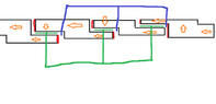
To put it in other words, is it possible to have such a design of a transformer where for example changes in current in primary coil cause induction in secondary coil but any power fed into secondary coil does not induce any changes in primary coil?The reason I ask this is because I am trying to figure out a magnetic core with an airgap and in this airgap will be a flat strip of conductor where I want Lorentz force to take effect on the electrons. I will have a primary coil on the magnetic core causing a changing magnetic field which will induce a changing B field within the airgap, so far so good. The problem is that I will also get current in the flat conductor strip which will then cause an impact on the B field within the core causing some reverse transformer action in my primary coil.
Because even though the metal strip is not like a coil wrapped around the core , once connected in a circuit it will still form a single loop around the core in a sense so any changes in current in this circuit will affect the primary.
 
Physics news on Phys.org
  • #2
If your requirement is for frequencies higher than mains (high RF / microwave frequencies) then a Circulator or Isolator could do what you want. It's based on non linear ferrite, I believe. But I'm afraid I don't know of anything similar that would work at mains frequencies.
 
  • #3
Can you give more detail as to what you are trying to accomplish? It seems to me, for instance, that one embodiment would be to simply drive the core into saturation using the primary. Are there requirements for linearity? (Etc.)
 
  • Like
Likes sophiecentaur
  • #4
sophiecentaur said:
If your requirement is for frequencies higher than mains (high RF / microwave frequencies) then a Circulator or Isolator could do what you want.
Yes my intended frequency range would be RF, in fact the whole range a given ferrite core could utilize which in some specific cases could go from tens of Mhz to few Ghz.
hutchphd said:
Can you give more detail as to what you are trying to accomplish? It seems to me, for instance, that one embodiment would be to simply drive the core into saturation using the primary. Are there requirements for linearity?
Ideally linearity , at least , up to as close as a non saturation driven ferrite core can give yes would be welcomed.
Anyway I am somewhat familiar with circulators etc and I think they would not match for my application.
Per @hutchphd question I am explaining further.
Idea is theoretically simple. I have a core and a coil on the core, the whole arrangement being wideband somewhat like a wideband balun only this is not a balun operation. So I drive the coil with varying RF frequency per my need and my core develops flux , there is now flux at the airgap ,. this flux passes a conductor of certain thickness and width (most likely a litz planar strip or similar) now there is some corresponding RF induced in my secondary loop which the one circuit that connects to the strip passing the core flux in the airgap.
What I would want is for this secondary current to not affect the flux in my core in any way.
So that only the primary coil induced current affects the core flux but not the current in the secondary circuit of which the strip passing the core airgap is one part.
I have thought of different geometries for the core and strip loop but I can't come up with anyone that would function only in the direction that I specified, especially if I have multiple strips and multiple cores stacked together whereby each strip and it's associated circuit forms a single loop or a half loop around the core anyway.

I would ideally go for a simple wire coil and core setup and not a specific waveguide/circulator waveguide one as that would severely limit the frequency range.I made a rather appalling sketch in MS paint (see attached) to explain in bit more detail my own attempt at this. You can see a multiple parallel core like structure which is toroidal but made up of small individual cores (black rectangular boxes) , the viewer is looking at the sructure from the outer side of it, the orange arrows show the B field in the cores. The red lines at the ends are conducting solid copper "field stoppers" so that the field leaps in the direction envisioned by the arrows and not just straight , the copper stops the field with eddy current induced back EMF.
The green lines represent the conductor strips in the airgaps of the core. The flux crosses the green conductors in the airgaps. the blue/purple lines represent the primary coil.
As you can see any current in the purple wires will induce flux in the core as the wires loop the core, but so do the green strips in the airgaps so current in those will induce also flux in the core which is what I don't want.
 

Attachments

  • fer core attempt.png
    fer core attempt.png
    8.2 KB · Views: 83
  • #5
artis said:
Ideally linearity
The linearity of the UHF circulators I used was good, as far as intermodulation products was concerned with power levels of tens of Watts iirc. If you know the details of what you want then look at the available units. Isolation can be good.
I would say that you are unlikely to get hold of a circulator (indeed anything!) to cover the whole range of frequencies you are considering so you might need a drawer full of different units - haha.
 
  • #7
artis said:
Anyway I am somewhat familiar with circulators etc and I think they would not match for my application.
Fair enough - circulators work because of the impedance involved (iirc) and rotating the polarisation of the signal passing through. I imagine that limits the application.
I / we weren't aware of the details of your requirement.
Construction of could be a bit fiddly, though.
 
  • #8
hutchphd said:
the magnetic flux in the core is independent of the secondary loading so long as the magnetic coupling is 100%.
Well in fact this is not my problem, here is why I think so.
Now suppose the current in my primary ramps up in the positive half cycle, the flux in my core increases , also the flux in my airgap increases. So far so good. Now due to the design of this circuit the increased flux creates a Lorentz force in the conductor in the airgap, there is a sense element in the secondary circuit so that it generates current proportionally to the field strength in the airgap.
The problem is that due to the way this airgap conductor wraps around the core that a current in it will create additional flux in the core. This will result in a situation where the primary current goes down in the positive half cycle but now the current in the secondary creates additional flux in the same direction so the current in the circuit doesn't go down, a feedback is established which now makes the current in the circuit DC and the flux in the core steady and not changing.
Due to the current in this secondary being stronger than the one in primary the primary current won't be able to change this steady state.What I would like is for it work like this - primary coil current (RF) creates an RF flux in the core, this flux also exists in the airgap , the secondary senses this flux and generates a current that is in phase with the flux in the airgap, as the flux in the airgap decreases the current in the conductor in the airgap also experiences decreasing current. But as I said this cannot happen if the conductor in the airgap continues to create flux in the core because that flux would then exist in the airgap and the current in the conductor following this airgap flux would never cease due to feedback.
 
  • #9
artis said:
(most likely a litz planar strip or similar)
What is the geometry of this ? (I understand Litz wire) Why is this not just a transformer?
The mathematics for the transformer is perhaps surprising but straightforward (no hand-waving required).
 
  • Haha
Likes sysprog
  • #10
hutchphd said:
What is the geometry of this ? (I understand Litz wire) Why is this not just a transformer?
The mathematics for the transformer is perhaps surprising but straightforward (no hand-waving required).
Well this is exactly the problem I am trying to avoid - this being a transformer. All I want is flux in an airgap where a B field cuts a conductor at 90 degrees and that's it. I can get that flux from a core and a coil wrapped around it - which so far is just an inductor with an airgap.
The problem starts when the conductor that traverses the inductor airgap starts to generate current. The conductor forming a loop will also induce some flux in the core, either in the same direction as the primary or in opposite direction. Both are problematic, if in the same direction then I get what I described above, original primary flux gets increased and then never ceases forming a steady DC state , opposite flux cancels the primary one which being rather small would create a condition where there is almost no flux.
 
  • #11
My understanding of transformers is that the secondary current has no effect on flux. So the conditions should remain stable. I have tested this using a transformer wound on a pair of C-cores which are slightly spaced, and a chemical balance to measure the force between them. When the secondary resistance is altered, the pull between the cores does not change.
 
  • #12
tech99 said:
My understanding of transformers is that the secondary current has no effect on flux.
But the secondary voltage does. So for this to work, I think you'll want a very low load impedance, like the way good current sensing transformers work.
 
  • #13
OK, first, I'll confess that I haven't read carefully enough to really understand the problem (geometry, etc.).

If you are worried about a "sensing" coil disturbing the state of the magnetic circuit, I wonder if you couldn't build yet another winding with a servo control to cancel whatever the sense winding is doing. It's simple at low frequencies, not so simple at higher frequencies and/or wide bandwidths.
 
  • #14
tech99 said:
My understanding of transformers is that the secondary current has no effect on flux.
That is not quite true. The flux in the core is independent of the impedance attached to the secondary. See #6 above and previous threads.

So I have no idea WTF we are discussing.
 
  • #15
hutchphd said:
The flux in the core is independent of the impedance attached to the secondary.
Only for a transformer with perfect coupling. Otherwise any additional increase in current from the source flowing through the primary leakage inductance will lower the voltage that the core sees. Refer to the equivalent circuit shown in this post (a t-section model, with the core represented by Lm, the magnetizing inductance). If the secondary load is low (high Z) compared to the leakage inductance, then there is no effect.
 
  • #16
Yes the result quoted was for perfect coupling as noted there. But isn't this geometry here essentially a torus? Do the air gaps bleed flux? Obviously I don't think so but need convincing
 
  • #17
Now from what I understand the flux is the result of primary Volts x turns , I can agree that the secondary doesn't change the total flux in the core, an increase in secondary current simply means an increase in primary current the net flux balances out ideally and stays the same.

My problem is bit different , is the secondary is also a "generator" not just a load, and if the current in the secondary follows the core flux , then upon the primary winding reaching maximum amplitude and core having max flux the secondary would also tend to follow that , the result being that the secondary now produces constant current which then saturates the core and changes in primary no longer affect secondary.
I think this is a property of every transformer that you can "drive" the core from both sides whether primary or secondary equally. In other words if you apply a DC value to the secondary for whatever reason and this value is strong enough to saturate or near saturate the core without allowing the flux to return to zero then changes in primary no longer affect secondary.

My question basically was whether it is possible to create a transformer where you could in theory have secondary current that is independent from core flux with the sidenote that the secondary doesn't need to be linked by core flux but it only needs to cross an airgap in the core so that the core B field cuts the conductor at 90 degrees.
This is my whole point. I think I know the answer already that for a traditional transformer it is impossible to have a secondary winding the current in which would not affect the core flux but how about a secondary winding that isn't a winding but merely a conductor that has to cross the core through an airgap in it, yet doesn't have to be linked/looped by the core, because I am not trying to cause induction in the secondary merely for part of it to experience a Lorentz force from primary flux in the core.
 
  • #18
artis said:
My question basically was whether it is possible to create a transformer where you could in theory have secondary current that is independent from core flux with the sidenote that the secondary doesn't need to be linked by core flux but it only needs to cross an airgap in the core so that the core B field cuts the conductor at 90 degrees.
The answer is emphatically no.
If the secondary is independent from the core flux then it is not a transformer!
Do you think that there is no magnetic flux across the air gaps?
Frankly I do not understand your diagram at all. The "wires"do not make circuits so what flux are you describing?

1636205522979.png
 
  • Like
Likes DaveE
  • #19
hutchphd said:
Frankly I do not understand your diagram at all. The "wires"do not make circuits so what flux are you describing?
Yes pardon my drawing skills. The blue wires are meant to represent normal wires that loop around the core as seen in the drawing, they are all connected together to represent they are in parallel but that is beyond the point.
The green flat lines represent a think flat conductor located in the airgap of the cores, the green wires attaching to these green flat strips simply represent wires attaching at the bottom and top of the strip and then going away forming a closed circuit.
Now I actually don't need for this to work as a transformer , in fact the transformer effect is unwanted in my case. I only needed a core that gives flux in an airgap so that I can then use that flux for my flat conductors.
The problem - the fact that when closing a circuit with these flat conductors they seems to form a loop similar to that of the primary (blue) around the cores and any current in the might generate additional flux in the core, if DC it could saturate the core or lower it's usable permeability.
 
  • #20
artis said:
how about a secondary winding that isn't a winding but merely a conductor that has to cross the core through an airgap in it, yet doesn't have to be linked/looped by the core
Current must flow in that secondary wire to get a Lorentz force. That means it must loop back to the source to make a closed circuit. If that loop encloses any of the flux in the core you have made a transformer. There is no such thing as a circuit that links flux in the core but isn't a loop. OK maybe it's a really big loop that is mostly outside of the B-field, but it's still a loop.

I suspect that your solution is to make a very high impedance current source to drive the secondary winding (the one in the gap) so that it's current doesn't change when the primary induces voltage in it as the flux changes. Then, of course, this would be combined (compared with) with a very low impedance voltage source driving the primary. This, theoretically, won't change the flux in the core because it will appear as an open circuit to the primary.

But, in spite of the several attempts you've made to describe your system, I still don't really understand either the geometry or the circuits. Perhaps I'm too lazy to read that carefully.
 
  • #21
DaveE said:
But, in spite of the several attempts you've made to describe your system, I still don't really understand either the geometry or the circuits. Perhaps I'm too lazy to read that carefully.
It's funny , maybe you won't fully understand my system but I think I fully understood what you are saying and combined with what I already know I think you are right , the basic fact here is this
DaveE said:
There is no such thing as a circuit that links flux in the core but isn't a loop.
I think this is what spoils it and what I already suspected because once I made a drawing I saw this loop being there, and I cannot put a very high impedance in the secondary sadly.
 
  • #22
I believe we are all more or less on the same page. In an ordinary transformer, supplying an auxiliary DC bias to the "secondary" can indeed drive the core flux to saturation and then all bets are off. The cancellation effect for flux is only for AC in the linear range.
 
  • Like
Likes DaveE

What is a One Direction Transformer?

A One Direction Transformer is a type of transformer used in electrical systems to convert high voltage electricity to lower voltage electricity, or vice versa, in a single direction.

How does a One Direction Transformer work?

A One Direction Transformer works by using two separate coils of wire, known as the primary and secondary coils, which are wrapped around a metal core. When an alternating current flows through the primary coil, it creates a changing magnetic field which induces a current in the secondary coil, thus transforming the voltage.

What are the advantages of using a One Direction Transformer?

The main advantage of using a One Direction Transformer is that it allows for the conversion of electricity in a single direction, which is useful for specific applications such as in rectifiers or DC power supplies. It also tends to be more efficient and have a smaller size compared to other types of transformers.

What are the limitations of a One Direction Transformer?

One limitation of a One Direction Transformer is that it can only convert electricity in a single direction, which means it is not suitable for applications that require bi-directional power flow. Additionally, it may be more expensive to manufacture compared to other types of transformers.

What are some common uses for a One Direction Transformer?

One Direction Transformers are commonly used in rectifiers, DC power supplies, and electronic devices that require a specific voltage conversion in a single direction. They are also used in power transmission and distribution systems to regulate voltage levels.

Similar threads

  • Electromagnetism
Replies
16
Views
1K
  • Electromagnetism
Replies
2
Views
2K
Replies
1
Views
64
Replies
17
Views
1K
Replies
3
Views
2K
Replies
1
Views
2K
Replies
13
Views
2K
Replies
10
Views
2K
  • Electromagnetism
Replies
25
Views
3K
  • Electromagnetism
Replies
2
Views
4K
Back
Top