- #1
PRITAM the cat of Ne
- 1
- 0
- Homework Statement
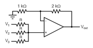
- What is the output voltage Vo of the OPAMP circuit given below?
- Relevant Equations
- V=IR
 THE ANSWER IS GIVEN: 6V, but according to me as the positive terminal is grounded the negative terminal will be virtually grounded (0V), from ohm's law (applying to the two series resistance) it is expected that Vo is 0V! I don't know where I am getting wrong!