Optimal Solution for Avoiding Cable Slip from Groove

  • Thread starter Krismein
  • Start date
  • Tags
    Cable Slip
In summary: This is accomplished by having a rotating component to the system (the fairlead), which provides a moment of inertia that resists the lateral forces. If the fairlead was not there, the cable would rotate around the rotation axis and the block would move.
  • #1
Krismein
12
1
Homework Statement
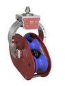
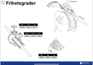
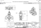
Which of the following fairleads will result in the best solution regarding a cables ability to stay in place (in the groove), when a force tries to “pull it out” of the groove? Friction is active in the connection surface of the cable and the fairlead.
Relevant Equations
ΣF=0
ΣM=0
M=F*arm
F_f=µ*F_N
v=ω*r
ω=2π*r*n
a_t=α*r
a_n=v^2/r
This is a theoretical question where we should explain and show with formulas which option is the best solution for avoiding cable to slip from groove. I believe that since the cable center is closer to the rotation axis (left fairlead), the force on the cable will move the fairlead as well (as the theoretical momentum is approximately zero). Making the cable stay in the groove. The second solution will with a rapid acting force create such a large momentum that the danger of the cable “slipping” from the groove is greater.

1648558629742.png
 
Physics news on Phys.org
  • #2
Welcome! :cool:

As I see it:
Same magnitude of lateral force will induce a greater rotational moment for the right hand arrangement, making the self-alignment easier and quicker (think of the mass of the pulley and its inertia respect to that lateral rotation).
 
  • Like
Likes Krismein
  • #3
Thanks for your reply! The inertia gets greater the longer the mass is from the rotating axis. Does this not mean that if the two fairleads have the same mass, it will be “easier“ to rotate the left fairlead? I am trying to figure out pros and cons with both sulutions, so any further views is much appreciated!
 
  • #4
Krismein said:
Thanks for your reply! The inertia gets greater the longer the mass is from the rotating axis. Does this not mean that if the two fairleads have the same mass, it will be “easier“ to rotate the left fairlead? I am trying to figure out pros and cons with both sulutions, so any further views is much appreciated!
You seem to be assuming the torque is the same in both cases. What force is tending to make the fairlead rotate, and where does it act?
 
  • Like
Likes Krismein and Lnewqban
  • #5
haruspex said:
You seem to be assuming the torque is the same in both cases. What force is tending to make the fairlead rotate, and where does it act?
The torque is occurring due to the vertical force acting on the cable. The momentum will be greater on the right fairlead, as well as the moment of inertia (simplification where only the cable and block has mass). The right fairlead will with the same acting force experience less torque, but also less moment of inertia.
 
Last edited:
  • #6
Krismein said:
The torque is occurring due to the vertical force acting on the cable.
I don't see how a vertical force is going to risk pulling the rope out of the groove, or how that would exert a torque about the axis of rotation.
 
  • #7
The question is based of a real problem that ocured during a marine Seismic survey. The convetional fairlead design is the right sketch. When the vessel is turning the widest fairleads will experience heeling, and it has occurred that the cable manages to “climb” the inside walls of the groove. I have attached two photos, where one is the right fairlead and the other shows heeling during operation.
1648588407384.jpeg

1648588457841.jpeg
 
  • #8
Krismein said:
The question is based of a real problem that ocured during a marine Seismic survey. The convetional fairlead design is the right sketch. When the vessel is turning the widest fairleads will experience heeling, and it has occurred that the cable manages to “climb” the inside walls of the groove. I have attached two photos, where one is the right fairlead and the other shows heeling during operation.
View attachment 299104
View attachment 299105
Fine, but you don’t seem to understand how a fairlead works. Why does it swivel? What is different about the forces during heeling?
 
  • #9
Please do tell me how it works.
My view is that the cable will stay in the groove and rotate around the fixed axis with the fairlead, as long as the static friction between the cable and groove surface is equal to the applied force. When the cable slips and travels up the grooved walls, the force acting on the fairlead from the cable will due to the momentum from the forces distance to the rotation axis move the block. I am not quite shure however, and I am struggling to theoretically prove which design is better to keep the cable in the groove.
The tention on the cable will rise during heeling, resulting in greater force.
 
  • #10
Krismein said:
Please do tell me how it works.
My view is that the cable will stay in the groove and rotate around the fixed axis with the fairlead, as long as the static friction between the cable and groove surface is equal to the applied force. When the cable slips and travels up the grooved walls, the force acting on the fairlead from the cable will due to the momentum from the forces distance to the rotation axis move the block. I am not quite shure however, and I am struggling to theoretically prove which design is better to keep the cable in the groove.
The tention on the cable will rise during heeling, resulting in greater force.
The reason for having a fairlead is that there are lateral forces tending to pull the rope sideways wrt the pulley, e.g. if the ship heels. If the pulley were rigidly mounted on the ship then the pulley would rotate sideways while the tension in the rope (suspending something?) stays vertical; or in another context the load might swing sideways.

The swivel allows the pulley to rotate sideways too so that the tension in the rope always pulls it down into the groove and not against the side of the groove.

I'm not sure what is likely to make this fail. If the load swings sideways suddenly and the pulley has a high moment of inertia wrt to the swivel axis (not the pulley's axis) then that could cause a problem.
But if the ship heels and the load stays vertical then you want the pulley to rotate on its swivel so as to remain vertical, so a high moment of inertia is not a problem.

There could also be subtle interactions between the rope and the pulley as the rope passes through it. Some magnetic tape cassettes used barrel shaped idler capstans. It was found that with a straight-sided or dished capstan if the tape drifted a little off centre then the edge of the tape further from the centre pulled tighter on the capstan, and this was a positive feedback, pulling the tape further to one side. But I don't see that happening with a rope of, presumably, circular cross section.
 
Last edited:
  • Like
Likes Lnewqban
  • #11
Krismein said:
The question is based on a real problem that occurred during a marine Seismic survey. The conventional fairlead design is the right sketch. When the vessel is turning the widest fairleads will experience heeling, and it has occurred that the cable manages to “climb” the inside walls of the groove. I have attached two photos, where one is the right fairlead and the other shows heeling during operation.
Would you mind explaining the quoted text in color a little more?
Does the second picture show the actual problem?
 
  • #12
Generally, a fairlead has little clearance between the cable/rope (line) and the housing, thus leaving no room for the line to leave the pulley.

If this is not possible for your situation, the pulley profile on the left (deep groove with vertical sides) will be more forgiving than the tapered sides of the right pulley. Think pushing a block against a wall versus pushing a block up a ramp.

There are also "4 Roller" fairleads often used on off-road vehicles.
952a-7356a6205534.__CR68,0,329,438_PT0_SX300_V1___.jpg

(photo from:
https://www.amazon.com/dp/B01GFAOUPY/?tag=pfamazon01-20)

Cheers,
Tom
 
  • Like
Likes Krismein
  • #13
I had trouble figuring out the picture at first, but now I think I see it.

Look at the very left of the picture. We see the rope going off the edge of the picture at a shallower angle than the angle made by the pulley. This implies to me that the problem is the combination of the weight of the pulley and its somewhat open V shaped groove. As @Tom.G notes, a more U shaped groove should work better.

But that is not the main difference between the two models in post #1. I worry that in the left hand model the ring will not slide easily through the bearings. The torque as the load shifts sideways will lead to high (opposing) vertical normal forces on the bearings, and with a bit of corrosion from the harsh marine conditions that would soon become a major problem. Moreover, should the rope climb out of the groove in that model you will be really stuck; it will be extremely difficult get it back in while under tension.

So I advise the RH model but with a U shaped groove, or the four roller model Tom.G shows. Another possibility would be as the RH model but with the centre of rotation in line with the pulley axle, if such an option exists.
 
  • Like
Likes Krismein
  • #14
Lnewqban said:
Would you mind explaining the quoted text in color a little more?
Does the second picture show the actual problem?
https://repository.am.szczecin.pl/b...9/1186/30-zn-am-45-117-walus-p.pdf?sequence=1
^ paper regarding the operation.

The picture shows the heeling i mentioned. If you look at the cable on the left fairlead, it is no longer positioned in the groove.

Quoting from the source:
“Usually, seismic vessels conduct turns by following a circular track. The turns are preplanned so that they begin and finish at specific points over ground: position of EOL (end of line) and position of SOL (start of line) (Figure 6). Therefore, when conduct- ing a turn, a seismic ship usually follows a circular path with a steady radius over ground. This method of turning is in many cases not efficient because it does not take into account the direction and speed of current. An ineffective method of turning may also increase stress on the gear and affect the geometry of the spread.”
The paper explains more about the situation.
 
Last edited:
  • Like
Likes Lnewqban
  • #15
Thank you, very interesting.

It seems that the weight of each pulley is the problem.
The tension in the cable is not enough to make the pulley fully aligned with it, the more horizontal the worst.

There is then a component of the net force that makes the cable move from the bottom of the groove, the more fluctuation of the tension (as usual in this type of operation), the more swinging of the pulley and the less the cable tend to stay in place.

I will try making a diagram of forces as soon as I have time.
If feasible, counter-balancing each pulley, rather than reducing the swing arm, may aliviate the current problem
 
  • Like
Likes Krismein
  • #16
Lnewqban said:
counter-balancing each pulley
I would think that is impractical. The counter balance would interfere with whatever the pulley hangs from.
 
  • #17
Lnewqban said:
Thank you, very interesting.

It seems that the weight of each pulley is the problem.
The tension in the cable is not enough to make the pulley fully aligned with it, the more horizontal the worst.

There is then a component of the net force that makes the cable move from the bottom of the groove, the more fluctuation of the tension (as usual in this type of operation), the more swinging of the pulley and the less the cable tend to stay in place.

I will try making a diagram of forces as soon as I have time.
If feasible, counter-balancing each pulley, rather than reducing the swing arm, may aliviate the current problem
That would be helpful, thanks!
 
  • #18
some CAD models and illustrations of the two fairleads.
 

Attachments

  • CE8B85CA-D797-41DE-98AA-192A8F8918BF.jpeg
    CE8B85CA-D797-41DE-98AA-192A8F8918BF.jpeg
    19.5 KB · Views: 67
  • 293424B9-71CC-4809-AB7D-DB0EABDA2D1E.png
    293424B9-71CC-4809-AB7D-DB0EABDA2D1E.png
    32.3 KB · Views: 55
  • A6602C74-79D4-4EAB-BD65-BDC1E4DA7AFA.png
    A6602C74-79D4-4EAB-BD65-BDC1E4DA7AFA.png
    54.6 KB · Views: 53

1. What is "Optimal Solution for Avoiding Cable Slip from Groove"?

The "Optimal Solution for Avoiding Cable Slip from Groove" refers to the most effective method for preventing cables from slipping out of grooves or channels, which can cause damage or malfunction in electronic devices or machinery.

2. Why is it important to avoid cable slip from groove?

Cable slip from groove can lead to various issues such as signal loss, equipment failure, and safety hazards. It is important to prevent cable slip to ensure proper functioning of electronic devices and machinery, as well as to avoid potential accidents.

3. What are the common causes of cable slip from groove?

Some common causes of cable slip from groove include improper cable routing, inadequate tension, and environmental factors such as temperature and humidity. It can also be caused by worn out or damaged grooves or cables.

4. What are some effective solutions for avoiding cable slip from groove?

Some effective solutions for avoiding cable slip from groove include using cable ties or clamps to secure the cable in place, using cable clips or holders to guide the cable along the groove, and using adhesive or non-slip materials to line the groove.

5. Are there any specific considerations for choosing the optimal solution for avoiding cable slip from groove?

Yes, the optimal solution may vary depending on the specific application and environment. Factors such as the type of cable, the weight and tension of the cable, and the material and condition of the groove should be taken into consideration when choosing the best solution for avoiding cable slip.

Similar threads

  • Introductory Physics Homework Help
Replies
12
Views
1K
  • Introductory Physics Homework Help
Replies
1
Views
282
  • Introductory Physics Homework Help
Replies
2
Views
1K
  • Introductory Physics Homework Help
Replies
17
Views
3K
  • Introductory Physics Homework Help
Replies
8
Views
4K
  • Introductory Physics Homework Help
Replies
4
Views
4K
  • Introductory Physics Homework Help
Replies
12
Views
5K
  • Introductory Physics Homework Help
Replies
4
Views
1K
  • Introductory Physics Homework Help
Replies
14
Views
1K
  • Introductory Physics Homework Help
Replies
1
Views
1K
Back
Top