Order of calculations for an air bubble system for dock de-icing

In summary, the person is trying to create an air bubble system to protect stationary docks from ice heave or ice jacking. They are confused as to the order of calculations, and have been going in circles in an attempt to calculate the amount and diameter of orifices to drill so as to utilize an energy efficient linear diaphragm compressor. They have no particular model selected, but have chosen one below as an example. There are two docks to protect, and this is their current design layout. Both loops are identical, and pressure drops from pipe and fittings appear to be insignificant based on the tools they used to calculate. They plan to drill 28 holes per loop for a total of 56 holes.
  • #1
downeast
11
11
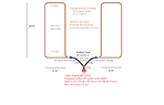
My current project involves constructing an air bubble system to protect stationary docks from ice heave or ice jacking during the winter months. Ice jacking is the vertical lift as ice expands. When this grabs piles supporting stationary docks, it can wreak havoc.

I am mainly confused as to the order of calculations, and have been going in circles in an attempt at calculating the amount and diameter of orifices to drill so as to utilize an energy efficient linear diaphragm compressor. I have no particular model selected, but have chosen one below as an example. There are two docks to protect, and this is my current design layout. Both loops are identical, and pressure drops from pipe and fittings appear to be insignificant based on the tools I used to calculate. 28 holes per loop for a total of 56 holes.

1640024462069.png


This is one pump's performance curve, and I just added a few notes to the printed material:

1640024784465.png

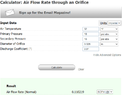
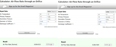
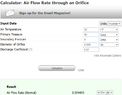
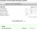
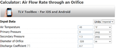
Regarding orifice diameter air flow, this is the online tool I've been playing with:
https://www.tlv.com/global/US/calculator/air-flow-rate-through-orifice.html

1640025948620.png


I left the defaults for temp and discharge coefficient, and put in:
1.3 psig secondary pressure (3 feet depth below water --> 36 in/27.7 = 1.3 psig)
0.028 inch orifice size (equal to the 0.7 mm holes I will drill about 2 ft OC).

This is where my confusion comes in. Given the compressor's performance curve, and given the 36 inch water depth, what should I use as the primary pressure? Increasing the pressure will increase the air flow result, and multiplying that by 56 holes gives me total consumption. But going to the pump's curve to find the corresponding psi at that cfm, I get a new psi. That new psi, plugged into the orifice diameter air flow tool, results in a new cfm per hole and a new total flow. Hence my endless loop in calculations.

I at least know that I can't be thinking about this correctly, and I have no background in this subject. Any guidance on the order of calculations I should be taking would be greatly appreciated!
 

Attachments

  • 1640024262735.png
    1640024262735.png
    13.1 KB · Views: 106
  • 1640025092009.png
    1640025092009.png
    18.1 KB · Views: 101
Last edited:
  • Like
Likes PhDeezNutz, jim mcnamara and berkeman
Engineering news on Phys.org
  • #2
There is more than one way to solve this problem. Here is one way.

1) You have selected an air pump, number of holes, and the depth of the pipe. The pressure drop through the holes needs to be high enough so that all holes will flow about the same amount of air. For a pipe depth of 3 feet, a hole pressure drop of 2 PSI should work. Then the total pressure drop at the pump will be 3.3 PSI.

2) The pump airflow is 4.0 CFM at 3.3 PSI. Divide that by 56 holes to get 0.071 CFM per hole.

3) You want 0.071 CFM per hole at 14.7 + 3.3 = 18.0 PSIA (PSI absolute) upstream pressure and 16.0 PSIA downstream pressure (2.0 PSI pressure drop). Use your orifice calculator to find the hole diameter. Your selection of orifice coefficient of 0.7 is a good number for a drilled hole, although 0.6 might be slightly better.

4) If your hole size corresponds to a standard drill size, you are done. Note that standard number drill sizes go down to #60 (0.040" diameter. Even smaller drills are available, but require special equipment and skill to use. Otherwise, go back to Step 1, make some changes, and repeat.

This problem needs to be solved by iteration unless you are very lucky in your initial guess for air pump and number of holes. Air pumps work best near the middle of their pump curves. The pump you selected is best operated between 2.5 and 4.0 CFM, although it can be operated outside that range.
 
Last edited:
  • Informative
  • Like
Likes downeast, berkeman and anorlunda
  • #3
Aha! I really appreciate you taking the time to explain in such detail!

So my key takeaways are:
  • Not only do I need enough pressure to get the air down to 3 ft, but I also need extra pressure to force the air through the holes and actually create bubbles, and a difference between primary and secondary of about 2 PSI should be ample.
  • Given the above, the pump needs to put out about 3.3 PSI, at which (per the performance curve) the airflow should be about 4.0 CFM. With 56 holes, that’s 0.071 CFM per hole.
  • Knowing this, experiment with the orifice tool across various standard drill bit hole sizes to see how close they get to 0.071 CFM. (also use 0.6 as the orifice coefficient since these holes are likely to be less than perfect).
Note: with my drill press I’ve tested from 1.10 mm to 0.60 mm, but settled on 0.70 mm (0.028 in) as the smallest to go without hiring out to a machine shop.

When using the orifice tool, I had psig as the inputs, with the secondary set to 1.3 psig (freshwater at 3 ft). But that number doesn’t include the air pressure at the surface. Also, I noticed that if I put in both primary and secondary as psig (pressure relative to the surface) like this:

1640057008816.png


If I simply change the units on the drop-down list to psi abs, the tool automatically adds in one atmosphere:

1640057116867.png


I just want to confirm, should I include 1 atmosphere in the both the primary and secondary inputs?

Lastly, rather than deviate from using 0.70 mm bits (for 0.028 inch holes), I may just drill less holes.

(0.0816 CFM/hole)(48 holes) = 3.92 CFM total. That’s only 4 holes less per loop, so I would take them out of the shore side leg of the loops (where the inlets are).

Again, I want to thank you very much for assisting me! Please let me know about the inputs to the orifice tool (PSIA on both, or just the primary).
 
Last edited:
  • #4
Possibly simpler:

You can buy orifices (orifi?) in a number of threaded bodies (8-32, 1/4-20...) and materials. You drill/tap the pipe for those (no .028" drills) and screw them in. This makes manufacturing simpler, performance more predictable, and allows you to replace the orifices if/when they get fouled. You can use a mix of sizes if you need more air in particular areas. This approach is probably more expensive, but is a lot more capable of coping with the real world.
 
  • Informative
  • Like
Likes Tom.G and berkeman
  • #5
Thanks for the suggestion. I looked into what jrmichler was referring to with regards to changing orifice coefficient from the default of 0.7 to 0.6. It would clearly be the second one below:

1640094920568.png

The -0.1 change in Cd made a significant difference with air flow calculation. I'm glad he pointed that out to me.

I like the control your suggestion provides, as well as the ability to change them out, but it might introduce a new variable with regards to turbulence, since they would likely protrude beyond pipe wall thickness (0.045 for 3/4 copper type L). I'll look into what's available (perhaps very short ones). A bit pricey at first glance but I really haven't looked at what's out there yet. Thanks again!

1640095702938.png
 
  • #6
downeast said:
I just want to confirm, should I include 1 atmosphere in the both the primary and secondary inputs?
One of the first steps in using any software package, or online calculator, is to learn exactly what the software is really doing. You can do some quick checks:

1) Setting the downstream pressure equal to upstream pressure to confirm that the software is adding 1 atmosphere to both equally.
2) Try the calculator with and without the 1 atmosphere, and compare to Bernoulli's equation: ##\Delta P = 0.5\rho V^2##. Note that density ##\rho## is the density of the air at the 3.3 PSIG (18.0 PSIA) pressure upstream of the orifice.
3) Run the calculator for a known orifice at a known pressure. Those orifices in your attachment are a good starting. Just be aware that the entrance holes may be chamfered, which affects the orifice coefficient.
 
  • #7
Hi,
The tool doesn't allow setting downstream and upstream pressure to same value, however if I set them both to 0 initially, and then change only the primary from psig to psi abs, it automatically adds 1 atmosphere to the primary before I even click on Calculate. Then when I run, it still returns the same error, so I assume it must be already including 1 atmosphere with the 0 psig of the secondary:

1640099920425.png


I tried the tool with and w/o the 1 atmosphere and the results are nearly identical.
1640100308244.png


Testing the tool with a known orifice returns the same results as provided this manufacturer, but only if I increase the Cd to 0.81. Perhaps I can find an orifice manufacturer that provides the Cd.

1640100981371.png

1640102230632.png


Lastly, these inputs all return nearly the same results:
(3.3 PSIG and 1.3 PSIG)
(18 PSIA and 1.3 PSIG)
(18 PSIA and 16 PSIA)

1640103055381.png


1640102903390.png
 

Attachments

  • 1640102512704.png
    1640102512704.png
    24.8 KB · Views: 107
  • 1640102129896.png
    1640102129896.png
    20.3 KB · Views: 87
  • 1640101075265.png
    1640101075265.png
    24.4 KB · Views: 98
  • 1640099342865.png
    1640099342865.png
    25.1 KB · Views: 91
  • Like
Likes jrmichler
  • #8
Dullard said:
You can use a mix of sizes if you need more air in particular areas. This approach is probably more expensive, but is a lot more capable of coping with the real world.
If you have a tight budget you can save by making your own set of replaceable orifices.

Buy plain end plugs with tapered threads from a plumbing supplier, in brass or plastic. Then drill them in a small lathe to the sizes you need for testing. Hold the plug in a female threaded fitting in the lathe chuck, with the drill bit in the tail-stock chuck.

You will need to drill and thread your pipe wall, but you can make more holes where needed later, and plug any holes you are not using.
 
  • #9
Sounds like a great way to not only customize or adjust later, but also avoid broken bits in the copper pipe at the same time. If you mess up a plug no big deal. However, certainly more labor. I wonder if a machine shop would prepare the plugs at a reasonable price. If so, could probably go to very micro hole sizes, approaching aeration applications as opposed to de-icing. Thanks for the tip- may come in handy for some future project!
 
  • #10
downeast said:
I wonder if a machine shop would prepare the plugs at a reasonable price.
There is a "Metal Mini Turning Lathe Machine" from China on eBay, costing less than US$250 that would drill the small holes.

There is probably one near you that could be borrowed, or someone to do the job for you. Ask around locally.
 
  • #11
I was also thinking of a getting a "Sensitive Drill Feed" that would help while using a drill press or lathe. I was able to drill to 0.60 mm w/o braking bits, but something like this would definitely help. The other problem is my press RPM's is under 5K, not even close to the 30K normally used on these micro mini bits.
 
  • #13
Hi all,

I just want to thank everyone for their tips and help with this, especially jrmichler who really pointed me in the right direction!

I purchased all the fittings, check valves and rubber hose. I'll decide on pump, thermostat and pressure relief valve after piping is installed and I test it with my portable compressor first. This is my final plan (I hope)!
1640228396939.png
 
  • Like
Likes jrmichler, Tom.G, anorlunda and 1 other person
  • #14
I'm not sure what you plan to do next. jrmilcher (accurately) said that there is more than 1 way to solve this problem. I am a bit more empirical (same basic premise), and use the Cv of the orifice (that value has all of the Italian math built in - 0.011 for an 0.028" knife-edge orifice) and a simple calc where flow is a function of dP, density, and Sg. I get similar (+/- 20%) flow values for your pressure conditions.

The wild card is the discharge coefficient. For my method, the Cv is different for different discharge coefficients, while it is explicit in jr's method. Bubble formation (all by itself) is interesting. The math for an orifice with different fluids at either side is beyond me. The 'instantaneous' discharge coefficient at an orifice where a bubble is forming depends (mostly) on the orifice geometry, but also on bubble size - the larger the bubble, the larger the coefficient. Bubble size depends on surface tension, finish, fluid viscosity,... If you understand that the orientation of the orifice (up, down, horizontal) will dictate different bubble sizes, then it follows that the orientation also changes the coefficient.

I'd test an instance of my exact arrangement before I bought too much stuff, Or I'd oversize the compressor and restrict the inlet to 'tune' it. I think of that as 'missing on the professional side.'
 
  • #15
Ha! Funny you should say this, and it did cross my mind. I haven't drilled any holes yet, and wanted to at least see bubble properties at a given diameter, depth and psi that will be close to actual. I plan on using the 0.7mm hole size in a short length of pipe in a garbage can of water. Depth will be only about 2'-3" or so, but it might at least let me know if the diameter of the hole is too large.

My only confidence in moving forward is that after reading many different forums where folks built similar de-icers, where they did little planning, used typically larger holes (1/32 inch), longer runs in smaller diameter hose or pipe, and did so across different depths (from 2 to 4 feet), they reported very good results.

My other issue is that our 10 mile long lake is currently in a 5 foot drawdown, which is done every 4 years. This is my best opportunity to lay the piping. The dam is now closed again and lake level will gradually return to normal by spring. I just spent the last couple of weeks releveling the two docks, which was a project in itself. They are supported by 6x6 posts, 6 per each 24 foot long dock, and this de-icing is just to protect those posts.

So given my time constraint, I want to at least get the piping in place, and test in the spring with my portable compressor set to a very low psi. At that point I'll decide on actual pump type, brand and sizing. I'm just hoping to be able to use an energy efficient linear diaphragm pump by making some pretty good predictions now.

I cleaned up my diagram a bit more, so might as well post it again. I really appreciate your advice!

1640274318210.png
 
  • Like
Likes Dullard

1. What is the purpose of calculating the order of operations for an air bubble system for dock de-icing?

The purpose of calculating the order of operations for an air bubble system is to ensure that the system functions efficiently and effectively in removing ice from a dock. By determining the correct order of operations, the system can be designed and operated in the most optimal way to achieve the desired results.

2. How is the order of operations determined for an air bubble system?

The order of operations for an air bubble system is determined by considering factors such as the size and shape of the dock, the temperature and depth of the water, and the power and capacity of the air compressor. It is also important to consider the position and spacing of the air bubble diffusers on the dock.

3. What is the recommended order of operations for an air bubble system for dock de-icing?

The recommended order of operations for an air bubble system for dock de-icing is to first activate the air compressor, followed by the release of air bubbles from the diffusers. This creates a flow of warm water from the bottom of the lake or river, which helps to melt the ice from underneath the dock. After a sufficient amount of time, the air bubbles can be turned off and the remaining ice can be removed manually.

4. Are there any safety precautions that should be considered when using an air bubble system for dock de-icing?

Yes, there are several safety precautions that should be considered when using an air bubble system for dock de-icing. It is important to ensure that the system is properly installed and maintained to prevent any malfunctions or accidents. It is also recommended to have warning signs or barriers in place to prevent people from coming into contact with the air bubbles or falling into the water.

5. Can the order of operations be adjusted for different weather conditions?

Yes, the order of operations can be adjusted for different weather conditions. For example, if the water is shallower or colder, it may be more effective to first use the air bubbles to create a flow of warm water, followed by manually removing the remaining ice. It is important to regularly assess and adjust the order of operations based on the specific conditions of the dock and surrounding environment.

Similar threads

Replies
1
Views
41
Replies
5
Views
2K
Replies
3
Views
347
Replies
15
Views
4K
Replies
6
Views
2K
  • General Engineering
Replies
2
Views
3K
Replies
3
Views
2K
Replies
13
Views
20K
Replies
2
Views
3K
Back
Top