Powering multiple devices in a low-voltage DC circuit

  • Thread starter Birck
  • Start date
  • Tags
    Multiple
In summary: For each device you must supply power within the specified limits.There are lots of different PS configurations to choose from. Without more information this is likely the best answer you are going to get.The answer to this sort of design problem ALWAYS begins with research. Get and read all of the datasheets, that is what EEs do first.In summary, if you need to power two or three different devices with low, but slightly different voltage requirements, you can do that by using a single powerful enough DC source. However, you will need to be aware of the power requirements and use a LDO (or its equivalent) to minimize voltage drops.
  • #1
Birck
9
3
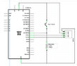
Hello, I'm putting together a shutter-speed testing device. I have the schematic at hand, but my question is this: If I need to power two or three different devices in a DC circuit, each with low, but slightly different voltage requirements, can I do that by using a single powerful enough DC source? If so, how do I separate out the outputs? By "low-voltage" I mean that nothing in the overall circuit requires more than 5 volts DC.
 
Engineering news on Phys.org
  • #2
Normally devices with different, incompatible, voltage requirements will require separate power supplies. OTOH, "slightly different" might be slightly OK. For each device you must supply power within the specified limits. There are lots of different PS configurations to choose from. Without more information this is likely the best answer you are going to get. The answer to this sort of design problem ALWAYS begins with research. Get and read all of the datasheets, that is what EEs do first.
 
  • Like
Likes russ_watters and Bystander
  • #3
Birck said:
how do I separate out the outputs?
There is an electric component called 'LDO' (or their equivalents) for this. Their input is a higher DC voltage, and they produce a lower one from it.
You need to be aware of the power requirements, because LDOs often require a heatsink.

It's common to have multiple LDOs (producing different voltages) on a single DC source.
 
  • #4
Thank you for the information. I will gather all the power requirements and get that info back to the forum.
 
  • #5
DaveE said:
Normally devices with different, incompatible, voltage requirements will require separate power supplies. OTOH, "slightly different" might be slightly OK. For each device you must supply power within the specified limits. There are lots of different PS configurations to choose from. Without more information this is likely the best answer you are going to get. The answer to this sort of design problem ALWAYS begins with research. Get and read all of the datasheets, that is what EEs do first.
Right. I need to get the specific power requirements together.
 
  • #6
I did some digging and found that I can probably get along without divvying up the supply voltage-the circuit I've been modeling mine on is based on an Arduino Mini, which has its own USB connector, and stays within the limits of USB power. The only other power required is for an LED (2.5volts?), and can be supplied by battery or by a single low-voltage source, which I can come up with. But thanks for pointing out the LDO. I'll find out what I can about them.
 
  • #7
Birck said:
The only other power required is for an LED (2.5volts?)
LEDs has their own tricks. They do have a 'voltage' (depending on current) but they require current, not voltage.

Try to check up on their usage.
 
  • #8
OK. Thanks for pointing that out.
 
  • #9
You are correct. It's easy to forget about the "diode" part of "led". I'm learning.
 
  • Like
Likes Tom.G and Rive
  • #10
within the low DC voltage range there are many linear regulators available in transistor cases that you simply need to provide a heatsink.
by using these you can have say a 12v DC line supply various loads on that line that require smaller voltages.
As long as the power isn't big, because then the regulators would heat up really bad + they only come within a limited current range. But for logic applications their suitable I think
 
  • #11
Thanks for that detail. So now I have two possible ways to deliver smaller voltages to more than one device- an LDO and a linear regulator. Or are they one and the same? Whichever, I know I also need a substantial heatsink, which I would not have thought of. Thanks again.
 
  • #12
Birck said:
Thanks for that detail. So now I have two possible ways to deliver smaller voltages to more than one device- an LDO and a linear regulator. Or are they one and the same? Whichever, I know I also need a substantial heatsink, which I would not have thought of. Thanks again.
Their the same almost, just think of a linear regulator. As long as you don't have high powers they work just fine, for high power applications and DC current you would need a switched regulator but that is a whole different ballgame

Now I could even try to give you examples if you told the specific voltages and amperages you need for each of your devices?
 
  • #13
Birck said:
So now I have two possible ways to deliver smaller voltages to more than one device- an LDO and a linear regulator. Or are they one and the same?
They are both linear voltage regulators (in contrast to switching voltage regulators), but they have important differences that you need to keep in mind when choosing which to use:
  • Standard (non-LDO) linear regulators will generally be less expensive than LDOs for the same power rating
  • LDOs are generally only used when the input-to-output voltage across the regulator is small, say a volt or two
  • LDOs have some quirky requirements that you have to be careful of (they use different transistor topologies inside in order to accomplish the low-dropout feature): they often have a minimum output current in order to remain stable, and they often cannot drive much output capacitance (so you are limited in how much decoupling capacitance you can put on that output voltage rail)
https://www.analog.com/en/design-ce...damentals-of-ldo-design-and-applications.html
 
Last edited:
  • Like
Likes artis and DaveE
  • #14
The only specifics I have are for one LED, alone, which requires 2.5-3 volts @ 20 mA. Far as I can tell, the rest of the circuit consists of a USB connector, an Arduino Micro microcontroller board, and a 4-pin OLED, requiring 2.8-5Volts (amps not indicated). The board itself draws 40 mA @ 7-10V. Photos of the circuit in operation show no other power source than USB.
 

Attachments

  • Screenshot 2023-07-31 at 11.13.44 AM.png
    Screenshot 2023-07-31 at 11.13.44 AM.png
    53.2 KB · Views: 51
  • Semi-schematic.jpg
    Semi-schematic.jpg
    28.2 KB · Views: 45
  • #15
If all you need to power is an Arduino and a LED, then I suggest match the voltage to the arduino and put a resistor in series with the LED.
Unless your LED is used for some very specific purpose, it will shine just fine within a certain range of voltages that don't need a LDO linear regulator but can be perfectly fine with a simple resistor.
As long as it's one LED and about 20mA a resistor dropping a couple of volts is manageable I think.
 
  • Like
Likes DaveE
  • #16
Thanks for your help. I should be able to manage that.
 
  • #17
For those just starting in electronics, here are further details for that LED resistor.

{[(Supply Volts) - (LED Volts)] / (LED Current)} = Resistor_value_in_Ohms

Or: R <ohms> = <volts_to_drop> / <amps_drawn>

Cheers,
Tom
 
  • #18
Birck said:
I'm putting together a shutter-speed testing device.
Birck said:
The only specifics I have are for one LED, alone, which requires 2.5-3 volts @ 20 mA. Far as I can tell, the rest of the circuit consists of a USB connector, an Arduino Micro microcontroller board, and a 4-pin OLED, requiring 2.8-5Volts (amps not indicated).
Can you say more about how you are going to measure the shutter speed? In your picture I think I see one Green LED aimed into the lens of your SLR camera, but I don't see anything to pick up the reflected light from that LED to let you know when the shutter is open or closed. Also, are you going to put a white reflector at the film plane (assuming it's a film SLR) to reflect the light that you shine into the lens when the shutter is open?

What is the function of the OLED? I see it in your schematic, but not in your picture...

1690928693868.png
 
  • #19
I think the OLED should be the display
The green thing is the phototransistor, and there should be an additional light source behind the camera somewhere. I guess it's about measuring the time of illumination through the open (mechanical) camera => shutter speed

I've suggested LDOs because of the mention of low voltage (it's usually a tight squeeze to use anything else in an 5V system, at least at amateur/beginner level) but this setup so far indeed requires just a single resistor to set the current of the additional LED..
 
Last edited:

1. How many devices can be powered in a low-voltage DC circuit?

The number of devices that can be powered in a low-voltage DC circuit depends on the total power consumption of the devices and the capacity of the power source. It is important to ensure that the total power consumption of the devices does not exceed the capacity of the power source to avoid overloading the circuit.

2. What is the maximum voltage that can be used in a low-voltage DC circuit?

The maximum voltage that can be used in a low-voltage DC circuit is typically 24 volts. This is because higher voltages can be dangerous and may require special safety precautions. It is important to consult the specifications of the devices and the power source to determine the appropriate voltage for the circuit.

3. Can different types of devices be powered in the same low-voltage DC circuit?

Yes, different types of devices can be powered in the same low-voltage DC circuit as long as the total power consumption does not exceed the capacity of the power source and the voltage is appropriate for all devices. It is important to consider the power requirements of each device and ensure compatibility before connecting them to the same circuit.

4. How can I ensure that all devices receive enough power in a low-voltage DC circuit?

To ensure that all devices receive enough power in a low-voltage DC circuit, it is important to calculate the total power consumption of the devices and choose a power source with a capacity that exceeds this value. It is also important to use proper wiring and connections to minimize power loss and ensure efficient distribution of power to all devices.

5. What are the potential risks of powering multiple devices in a low-voltage DC circuit?

The main risk of powering multiple devices in a low-voltage DC circuit is overloading the circuit, which can cause damage to the devices and potentially start a fire. It is important to carefully calculate the power requirements and use appropriate safety measures, such as fuses or circuit breakers, to prevent overloading. Additionally, incorrect wiring or connections can also pose a risk, so it is important to follow proper guidelines and consult a professional if needed.

Similar threads

Replies
3
Views
366
  • Electrical Engineering
Replies
32
Views
873
  • Electrical Engineering
Replies
8
Views
1K
Replies
61
Views
6K
  • Electrical Engineering
Replies
10
Views
999
  • Electrical Engineering
Replies
15
Views
633
Replies
6
Views
1K
Replies
2
Views
424
  • Electrical Engineering
Replies
7
Views
3K
Replies
6
Views
2K
Back
Top