Replacing 0603 Capacitors: Techniques and Challenges

  • Thread starter Ephant
  • Start date
  • #1
Ephant
135
2
Hi,

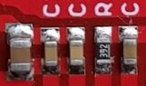
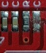
What techniques would it be possible to replace 0603 capacitors which has size only of 0.063 in x 0.031 in (smaller than a mosquito?) (see attached image with the C indicating the 0603 caps)

If this is extremely difficult, what services out there that can replace 3 or 4 0603 capacitors in single PCB only? If none, can anyone replace mine?

Also can one just replace 0603 capacitor with normal size capacitor with the same say 10 microFarah (and others)?
 

Attachments

  • 0603.jpg
    0603.jpg
    25.9 KB · Views: 44
Engineering news on Phys.org
  • #2
What kind of soldering iron(s) do you have? Do you have a hot air soldering station?

Do you have a desk magnifier (lens)?
 
  • Like
Likes Vanadium 50
  • #3
I have a desk magnifier and ordinary small tip hot iron soldering unit only. But as soon as I used, it, the plastics in the PCB just melted.
 
  • #4
Can you borrow a 2nd iron? What kind of iron do you have? I'm guessing it's not a Metcal...
 
  • #5
BTW, how do you know that this capacitor is bad? Did it fail open or short, or just change value?
 
  • #6
If it failed open, I'd leave it there. You still have the problem of attaching the replacement, but not the problem of getting the old one out.

Similarly, if something else, I'd consider destroying it with a tiny pair of diagonal cutters or similar rather than get it out. Desoldering is trickier than soldering.
 
  • Like
Likes phinds
  • #7
Vanadium 50 said:
I'd consider destroying it with a tiny pair of diagonal cutters or similar rather than get it out.
Dyking it off can delaminate the SMT pads, which can complicate adding back in a replacement.
 
  • #8
See my soldering set attached. I already used smaller tweezer to remove the old 0605 in the right most capacitor. I just wanted to change the values to alter the cut off frequencies. Can I just use an ordinary normal size capacitor and just solder the wire legs of them to the PCB?
 

Attachments

  • soldering set.jpg
    soldering set.jpg
    59.9 KB · Views: 31
  • 0603 removed.jpg
    0603 removed.jpg
    8.4 KB · Views: 29
  • #9
In my personal experience 1206 are reasonably easy to solder/replace (you just need magnifier and some testing to find the best temperature of the iron). I admit I never tried with the smaller ones but I know people who did and from what I remember they used exactly the same kind of soldering station and solder tip I have.

However, I am using a soldering station similar to the one on the picture - as far as I am aware it is a cheap clone of some successful design, can't remember details. $40 or less.

1700434974441.png
 
  • Like
Likes Ephant
  • #10
Ephant said:
I just wanted to change the values to alter the cut off frequencies.
Um, did you want to increase the capacitance?
 
  • #11
Ephant said:
See my soldering set attached.
That iron does not appear to be compatible with soldering small SMT components. You need a temprature-controlled soldering iron like the one @Borek posted or a Metcal unit.
 
  • Like
Likes Ephant and DaveE
  • #12
berkeman said:
Dyking it off can delaminate the SMT pad
Yup. But I'd take "might" over "will burn it up".

Obviously, SMT is not designed for anythng like what the OP wants to do. So it's an issue of what the "least worst" option is.
 
  • Like
Likes Ephant
  • #13
Without the right equipment it's next to impossible. A SMT hot air rework station is fairly cheap but good magnification and soldering tools are priceless.
IMG_20190721_074216425_HDR.jpg

1700438626966.png

1700438922928.png
 
  • Like
Likes Ephant and berkeman
  • #15
Or the lovely flat blade tips METCAL has for doing inline packages (SMTC-106, I think).
1700441803836.png
1700441803836.pngI use those to remove 0603 and 0805 components, particularly when not worried about the component's welfare. They clean the pads nicely also
 
  • Informative
  • Like
Likes DaveE and berkeman
  • #16
berkeman said:
Um, did you want to increase the capacitance?

I want to lower the capacitance. Why can't I use a big ceramic capacitor like in the attached picture? I can just easily solder the two legs in the pcb.

ceramic caps.JPG
 
  • #17
For rework purposes for testing, sure. For production purposes, obviously no.
 
  • Like
Likes nsaspook
  • #18
What's the application? Is it just a test board that you can muck around with. Can you achieve your goals with added capacitance? I'm really bad, but I've done on it test boards... it's a lot easier to just stack some caps on there to add capacitance if that's an option you can consider. I'm no way suggesting it's pretty or would meet any standards gosh I've had people arguing with me about things like flight qualifications I'm just trying to debug this broken board to figure out what's wrong and we can propose proper changes after... so if it's like just testing or proof of concept then why not :)

Below is not my picture I just Googled it to show you what I mean. Picture below is pretty extreme but it definitely gets the point across.
boi1v8wccaau5cs-jpg-large.jpg


If your application is really sensitive or you need to watch for certain resonances you can assume a slightly larger ESL series inductance for your modeling.
 
  • Haha
Likes hutchphd
  • #19
hutchphd said:
Or the lovely flat blade tips METCAL has for doing inline packages (SMTC-106, I think). View attachment 335800View attachment 335800I use those to remove 0603 and 0805 components, particularly when not worried about the component's welfare. They clean the pads nicely also
METCAL is an addiction. Once you pay the admission price it's never ending series of fixes. Most of the prototype boards use METCAL for soldering.

1700458204760.png

1700458292468.png

To the OP, good magnification and steady hands are a requirement of good results. If the iron is on the pad for more than 3 seconds, expect problems.

1700458570100.png
 
  • Like
Likes Ephant
  • #20
Reworking SMT boards takes some skill only acquired through practice. Also, as others have said, good tools (which your soldering iron isn't). I would try to find some scrap SMT PCBAs to practice on.
 
  • Like
Likes davenn, rbelli1 and nsaspook
  • #21
Joshy said:
What's the application? Is it just a test board that you can muck around with. Can you achieve your goals with added capacitance? I'm really bad, but I've done on it test boards... it's a lot easier to just stack some caps on there to add capacitance if that's an option you can consider. I'm no way suggesting it's pretty or would meet any standards gosh I've had people arguing with me about things like flight qualifications I'm just trying to debug this broken board to figure out what's wrong and we can propose proper changes after... so if it's like just testing or proof of concept then why not :)

Below is not my picture I just Googled it to show you what I mean. Picture below is pretty extreme but it definitely gets the point across.
View attachment 335829

If your application is really sensitive or you need to watch for certain resonances you can assume a slightly larger ESL series inductance for your modeling.

I want to decrease the the capacitance from 10 nanoFarad to 20 picoFarad. If the capacitance is decreased, what happens to the resonances if I put 20 picoFarad ceramic capacitor with wire legs that can easily solder to it?
 
  • #22
Oh, my suggestion wont work if you're trying to decrease the capacitance :( I think the earlier suggestions sound better you might want to consider those instead.

I recommend you share the application or maybe some of the schematic, or both. It might help with suggestions.
 
  • #23
Joshy said:
Oh, my suggestion wont work if you're trying to decrease the capacitance :( I think the earlier suggestions sound better you might want to consider those instead.

I recommend you share the application or maybe some of the schematic, or both. It might help with suggestions.

Please look at this schematic of the Olimex-EKG-EMG. I actually saw a web site how to modify it to increase the high frequency cut off from 40 Hz to 500 Hz (see below too). In my case. I want to increase the cut off to at least 1000 Hz.

https://www.olimex.com/Products/Duino/Shields/SHIELD-EKG-EMG/open-source-hardware

schematic of the product

https://www.olimex.com/Products/Dui.../resources/SHIELD-EKG-EMG-REV-B-SCHEMATIC.pdf

How to modify the Olimex from 40 Hz to 500 Hz.

https://www.ncbi.nlm.nih.gov/pmc/articles/PMC9143621/

I saw the following product from UFI (Biopotential 2122) with high frequency cut off of at least 1000 Hz (and higher but I need only 1000 Hz for now). But they are selling it to me for $1200.

https://www.ufiservingscience.com/datasheets/2122manual.pdf

If the capacitors in the Olimex is modified to 1000 Hz. Can it matches UFI Bioamplifier 2122 performance? Kindly study the Olimex schematics and comment if the components have the the best design also possibly matching even very high end unit or it is not up to it.

For this UFI 2122 description "Introduction The Model 2122 is a differential amplifier for use with low level signals -- 2 microvolts and above -- ranging from DC to 10 KHz. Primarily designed as biological instrumentation, the Model 2122 is well suited to many other demanding applications. It features high common mode rejection, high input impedance, low noise, small size, and excellent frequency response. The Model 2122i includes subject isolation, but is otherwise identical to the standard Model 2122."

".... Less than 2 μV peak to-peak, DC to 100 Hz with 10K Ohm source".

Can the Olimex also has 2 μV peak to-peak, DC to 100 Hz with 10K Ohm source noise? Is this a common specification of typical amplifier these days and can easily be achieved? What happens if the frequency is increased to 1000 Hz, what usually is the peak to peak noise in microvolt? (Have you encountered or heard)?

Some disclaimers:

I'm not newbie in bioamplifiers (I owned 5 EEG units and my simulators in my biology research lab), so please don't keep emphasizing plugging it to AC can electrocute me and stop this thread right away. I'd never plug it to AC. I used isolator. And in the Olimex, it's connected with laptop with battery only. Never the AC plugged in. To all users too. Always use isolator to prevent turning it into electric chair or just don't do any project like this unless you know what you are doing.

2nd. Don't convince me that there is nothing to see in the EMG at 1000 Hz. I'm not building an EMG which has limit only of 500 Hz. I'm getting a Biopotential amplifier with cut off of 1000 Hz to prove to myself the body plexuses or nerve centers can't emit high frequency that can be measured in surface mount biopotential sensors. Yes. This may sound ridiculous but as biologist, I need to prove it so kindly dont tell me not to get the circuit and just believe. Also No. I'd never use needle. It's all surface measurement of the biopotential so worry not about sticking needles and hurting the body. I 100% will not use needles.

3rd. Can you recommend other biopotential amplifier that has very good quality at 1000 Hz and can detect even very small EMG-like level (1 microVolt and so) signal at low noise and high common mode rejection with same or better quality that the UFI Biopotential 2122 ? I just need 1 channel. It's alternative to the UFI Biopotential 2122 which is selling me at $1200. Problem with it is they only accept credit cards and wire transfer. So since I don't want to share my credit card. I have to wire transfer but it is more hassled. If I can find something with same quality at it and pay online, then it is much more convenient.

Thank you so much guys!
 
  • #24
Thread closed for Moderation...
 
  • #25
Ephant said:
Can the Olimex also has 2 μV peak to-peak, DC to 100 Hz with 10K Ohm source noise? Is this a common specification of typical amplifier these days and can easily be achieved? What happens if the frequency is increased to 1000 Hz, what usually is the peak to peak noise in microvolt? (Have you encountered or heard)?
Ephant said:
I'm not newbie in bioamplifiers (I owned 5 EEG units and my simulators in my biology research lab)
Using biomedical equipment according to the manufacturer's guidelines is one thing, trying to modify or design your own biomedical instrumentation is another. I have done both, and the latter is a very involved process (including getting safety approvals per published standards).

I'm not comfortable with giving such advice here at PF, so this thread is now closed. Thanks all for your good rework advice and suggestions -- that part of the thread was fine.
 

What is an 0603 capacitor and where is it commonly used?

An 0603 capacitor refers to a surface mount capacitor with dimensions of 0.06 inches by 0.03 inches. It's a compact component widely used in electronic devices such as smartphones, laptops, and other digital equipment due to its small size and efficiency in space utilization. These capacitors are essential for stabilizing voltage and filtering signals within circuits.

What tools are required for replacing an 0603 capacitor?

To replace an 0603 capacitor, you'll need a fine-tip soldering iron, solder, flux, tweezers, a magnifying glass or microscope, and a desoldering pump or solder wick. These tools help ensure precise handling and effective soldering at the small scale of 0603 components.

What are the common challenges faced when replacing 0603 capacitors?

One of the main challenges is the small size of the capacitor, which requires precise handling and soldering techniques to avoid damaging the component or the circuit board. Additionally, the risk of thermal damage to the capacitor and surrounding components due to excessive heat exposure during soldering is significant. Ensuring proper placement and alignment can also be difficult without the aid of magnification tools.

How can one ensure proper alignment and placement of an 0603 capacitor during replacement?

Proper alignment and placement can be achieved by using a microscope or magnifying tool to accurately position the capacitor. It's crucial to align the capacitor correctly according to the polarity markings, if applicable, and ensure that it sits flat on the solder pads. Using tweezers, gently place the capacitor while applying minimal force to avoid shifting or damaging other nearby components.

What are some best practices for soldering an 0603 capacitor?

When soldering an 0603 capacitor, it's important to use a fine-tip soldering iron and apply a small amount of flux to improve the solder's flow. Heat the pad and the capacitor lead simultaneously for a short duration to avoid overheating. Apply a small amount of solder to form a strong, clean joint, and inspect the solder joint under magnification to ensure it is free of cold solder joints or bridges. Keeping the iron's temperature and contact time controlled helps prevent damage to the capacitor and the circuit board.

Similar threads

Replies
2
Views
964
  • Electrical Engineering
Replies
9
Views
2K
  • Electrical Engineering
Replies
20
Views
7K
Replies
34
Views
10K
  • Electrical Engineering
Replies
1
Views
2K
  • Electrical Engineering
Replies
12
Views
4K
  • Electromagnetism
Replies
28
Views
2K
  • Math Proof Training and Practice
3
Replies
100
Views
7K
Replies
13
Views
2K
  • Math Proof Training and Practice
2
Replies
56
Views
7K
Back
Top