- #1
Phynight
- 2
- 1
- TL;DR Summary
- Trying to figure out the forces involved in squishing a bit of metal between two wheels.
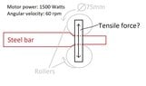
Hi, I'm building a rolling mill for flattening out bits of steel and I'm trying to make sure it's not going to break.
I know that with a 1500w motor geared down to 60rpm (2pi rad/s) i end up with 239Nm of torque.
239Nm working at a radius of 0.0375m gives 6369N of force generated at the edge of the rollers, but that's not the force that would be acting in the vertical plane because where the rollers touch the steel the forces would be mostly horizontal. Or is it? My gut tells me that the forces should be much bigger than that.
Thanks for any help.