- #1
hillbilly63
- 9
- 0
Summary:: What is the sliding resistance of an eccentrically loaded block on a flat surface?
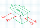
If a 1000kg block is placed on a flat surface (say coeff. of friction = 0.4), what force does it take to slide if it loaded eccentrically, i.e. at the far edge of the block?
My thinking is there is both rotation and translation to consider, but I can't come up with an answer that makes sense (at all!).
See the attached diagram - I 'know' that for force 2 & 3, the sliding resistance would be (1000x9.81/1000) x 0.4 = 3.92kN.
For forces 1 and 4 though, I'm scratching my head (a lot, and for quite some time now!). My intuition is also that force 1 would be lower than force 4, and both would be lower than 2 & 3.
(to clarify, the arrows are illustrating different load positions, not simultaneous loads)