- #1
Juanda
- 292
- 100
- TL;DR Summary
- I want to derive the formula for the transmission of torque through friction.
I am trying to obtain the expression for the potential transmission of torque using friction.
I could derive the formula assuming constant pressure between planar surfaces.

To have it in LATEX so it is easier to read, this is the expression for the torque transmission using friction.
$$\tau=\frac{2\mu N(r_M^3-r_m^3)}{3(r_M^2-r_m^2)}$$
This is the same as what I later found in this video of Youtube so I'm fairly confident that the result is correct.
(Note: He is using ##F## instead of ##N## for the normal force and also his disks are solid without a hole in the middle)

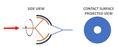
I'm now interested in knowing a similar but a little bit more complex case. Spherical contact instead of planar contact. Not necessarily half a sphere but that would be the case with the biggest contact patch.

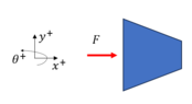
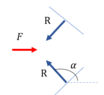
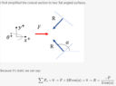
In this scenario, assuming a constant pressure makes less sense. As the contact patch becomes more tangential to the force, I assume the normal force between surfaces will decrease. How would you obtain the normal pressure between surfaces as a function of the angular position under study? Because of the rotational symmetry, I believe it'd be possible to express that function as ##\theta (r)## (see the diagram of the projected area) but I don't know how. Once that normal pressure is known, I hope to be able to derive the torque in a similar way as I did for the planar case.
I could derive the formula assuming constant pressure between planar surfaces.
To have it in LATEX so it is easier to read, this is the expression for the torque transmission using friction.
$$\tau=\frac{2\mu N(r_M^3-r_m^3)}{3(r_M^2-r_m^2)}$$
This is the same as what I later found in this video of Youtube so I'm fairly confident that the result is correct.
(Note: He is using ##F## instead of ##N## for the normal force and also his disks are solid without a hole in the middle)
I'm now interested in knowing a similar but a little bit more complex case. Spherical contact instead of planar contact. Not necessarily half a sphere but that would be the case with the biggest contact patch.
In this scenario, assuming a constant pressure makes less sense. As the contact patch becomes more tangential to the force, I assume the normal force between surfaces will decrease. How would you obtain the normal pressure between surfaces as a function of the angular position under study? Because of the rotational symmetry, I believe it'd be possible to express that function as ##\theta (r)## (see the diagram of the projected area) but I don't know how. Once that normal pressure is known, I hope to be able to derive the torque in a similar way as I did for the planar case.